PAGE 12
WS1TC & WS1.25 TC Manual Page 13
6
2
4b
4a
5
1
3
7
8
WS1TC Drive Cap Assembly, Down ow Piston, Regenerant Piston and Spacer Stack Assembly
Drawing No. Order No. Description Quantity
1 V3005 WS1 Spacer Stack Assembly 1
2 V3004 Drive Cap ASY 1
3 V3178 WS1 Drive Back Plate 1
4 V3011 WS1 Piston Down ow ASY 1
5 V3174 WS1 Regenerant Piston 1
6 V3135 O-ring 228 1
7 V3180 O-ring 337 1
8 V3105 O-ring 215 (Distributer Tube) 1
Not Shown
V3001 WS1 Body ASY Down ow
1
V3001-02 WS1 Mixing Valve Body ASY
Note: The regenerant piston is not used in backwash only applications.
Black Plug
4
6
5
3
7
WS1 & WS1.25 Drawings & Service Manual Page 5
Injector Cap, Injector Screen, Injector, Plug and O-Ring
1
2
3
4
5
Drawing No. Order No. Description Quantity
1 V3176 INJECTOR CAP 1
2 V3152 O-RING 135 1
3 V3177-01 INJECTOR SCREEN CAGE 1
4 V3010-1Z WS1 INJECTOR ASY Z PLUG 1
5
V3010-1A WS1 INJECTOR ASY A BLACK
1
V3010-1B WS1 INJECTOR ASY B BROWN
V3010-1C WS1 INJECTOR ASY C VIOLET
V3010-1D WS1 INJECTOR ASY D RED
V3010-1E WS1 INJECTOR ASY E WHITE
V3010-1F WS1 INJECTOR ASY F BLUE
V3010-1G WS1 INJECTOR ASY G YELLOW
V3010-1H WS1 INJECTOR ASY H GREEN
V3010-1I WS1 INJECTOR ASY I ORANGE
V3010-1J WS1 INJECTOR ASY J LIGHT BLUE
V3010-1K WS1 INJECTOR ASY K LIGHT
GREEN
Not Shown V3170 O-RING 011 *
Not Shown V3171 O-RING 013 *
* The injector plug and the injector each contain one 011 (lower) and 013 (upper) o-ring.
Note: For up ow position, injector is located in the up hole and injector plug is in the
other hole. WS1 up ow bodies are identi ed by having the DN marking removed.
Up ow option is not applicable to EE, EI, or TC control valves.
For a lter that only backwashes, injector plugs are located in both holes.
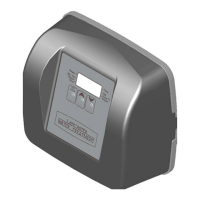
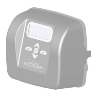
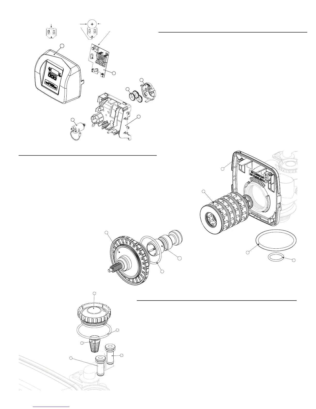
FRONT COVER AND DRIVE ASSEMBLY
Item No. Quantity Part No. Description
1 1 V4180 Front Cover Assembly
2 1 V3107 Motor
3 1 V3106 Drive Bracket/Spring Clip
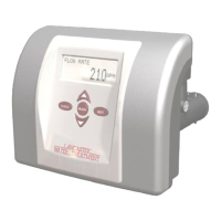
4 1 V3818TC PC Board
5 3 V3110 Drive Gear Cover
6 1 V32109 Drive Assembly
2-6 * V3002TC Drive Assembly (parts 2-6)
NOT
SHOWN
1 V3186 Transformer 110V-12V
INJECTOR, INJECTOR CAP, SCREEN AND O-RING
Item No. Quantity Part No. Description
1 1 V3176 Injector Cap
2 1 V3152 O-Ring 135
3 1 V3177 Injector Screen
4 1 V3010-1Z Injector Assy. Z Plug
NOT
SHOWN
* V3170 O-Ring 011
NOT
SHOWN
* V3171 O-Ring 013
* Injector plug and injector contains one 011 and one 013 O-ring
DRIVE CAP ASSEMBLY, DOWN FLOW PISTON, REGENERANT PISTON AND SPACER STACK ASSEMBLY
Item No. Quantity Part No. Description
1 1 V3005 Spacer Stack Assembly
2 1 V3004 Drive Cap Assembly
3 1 V3135 O-Ring 228
4 1 V3011 Piston Assembly
5 1 V3180 O-Ring 337
6 1 V3105 O-Ring 215
7 1 V3946 Backplate
WS1 & WS1.25 Drawings & Service Manual Page 5
Injector Cap, Injector Screen, Injector, Plug and O-Ring
1
2
3
4
5
Drawing No. Order No. Description Quantity
1 V3176 INJECTOR CAP 1
2 V3152 O-RING 135 1
3 V3177-01 INJECTOR SCREEN CAGE 1
4 V3010-1Z WS1 INJECTOR ASY Z PLUG 1
5
V3010-1A WS1 INJECTOR ASY A BLACK
1
V3010-1B WS1 INJECTOR ASY B BROWN
V3010-1C WS1 INJECTOR ASY C VIOLET
V3010-1D WS1 INJECTOR ASY D RED
V3010-1E WS1 INJECTOR ASY E WHITE
V3010-1F WS1 INJECTOR ASY F BLUE
V3010-1G WS1 INJECTOR ASY G YELLOW
V3010-1H WS1 INJECTOR ASY H GREEN
V3010-1I WS1 INJECTOR ASY I ORANGE
V3010-1J WS1 INJECTOR ASY J LIGHT BLUE
V3010-1K WS1 INJECTOR ASY K LIGHT
GREEN
Not Shown V3170 O-RING 011 *
Not Shown V3171 O-RING 013 *
* The injector plug and the injector each contain one 011 (lower) and 013 (upper) o-ring.
Note: For up ow position, injector is located in the up hole and injector plug is in the
other hole. WS1 up ow bodies are identi ed by having the DN marking removed.
Up ow option is not applicable to EE, EI, or TC control valves.
For a lter that only backwashes, injector plugs are located in both holes.
5
Page 12 WS1TC & WS1.25 TC Manual
Front Cover and Drive Assembly
* Drawing number parts 2 through 6 may be purchased as a complete assembly, part V3002.
Drawing No. Order No. Description Quantity
1 V3175TC-01 WS1TC FRONT COVER ASY 1
2 V3107-01 WS1 MOTOR ASY 1
3 V3106-01 WS1 DRIVE BRACKET & SPRING CLIP 1
4 V3818TC WS1TC PC BOARD 4-DIGIT 1
5 V3110 WS1 DRIVE REDUCING GEAR 12 X 36 3
6 V3109 WS1 DRIVE GEAR COVER 1
V3002TC WS1TC DRIVE ASY *
Not Shown V3186 WS1 AC ADAPTER 110V - 12V 1
Not Shown
V3186 WS1 AC ADAPTER 110V-12V
1
V3186EU WS1 AC ADAPTER 220-240V-12V EU
V3186UK WS1 AC ADAPTER 220-240V-12V UK
V3186-01 WS1 AC ADAPTER CORD ONLY
1
2
3
4
5
6
Battery Fully Seated
When replacing the battery, align
positives and push down to fully seat.
Correct
Battery
Orienta-
tion
Battery replacement is
3 volt lithium coin cell
type 2032.
1
 Loading...