User Guide User Guide
Page 23PP307 Page 23PP307
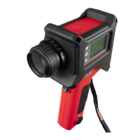
In its simplest form, SOLOnet consists of a thermometer and cable, providing
the user with process control and monitoring via traditional current and contact-
closure I/O.
Fig. 13 - Typical Current and Contact-closure (Non-Ethernet) Installation
307014
SOLOnet SYSTEM
PLANT
SOLOnet
Thermometer
0 or 4 to 20mA
Temperature
Output
0 to 20mA
Emissivity/NG
Input
Alarm Contact-
closure Outputs
Command
Contact-closure
Input
Laser Activate
Contact-closure
Input
Thermometer
Supply
24V d.c.
Remote User
Switch
Temperature
Indicator
Analog PLC
Fig. 14 - Schematic Diagram for a Typical Current and Contact-closure
(Non-Ethernet) Installation
5.1 Typical Current and Contact-closure (Non-Ethernet) Installation
SOLOnet
Thermometer
Customer Terminal Array
SOLOnet Cable
Temperature Indicator
Analog PLC
To Power Supply (24V d.c.)
To Remote Laser Switch
307013
In its simplest form, SOLOnet consists of a thermometer and cable, providing
the user with process control and monitoring via traditional current and contact-
closure I/O.
Fig. 13 - Typical Current and Contact-closure (Non-Ethernet) Installation
307014
SOLOnet SYSTEM
PLANT
SOLOnet
Thermometer
0 or 4 to 20mA
Temperature
Output
0 to 20mA
Emissivity/NG
Input
Alarm Contact-
closure Outputs
Command
Contact-closure
Input
Laser Activate
Contact-closure
Input
Thermometer
Supply
24V d.c.
Remote User
Switch
Temperature
Indicator
Analog PLC
Fig. 14 - Schematic Diagram for a Typical Current and Contact-closure
(Non-Ethernet) Installation
5.1 Typical Current and Contact-closure (Non-Ethernet) Installation
SOLOnet
Thermometer
Customer Terminal Array
SOLOnet Cable
Temperature Indicator
Analog PLC
To Power Supply (24V d.c.)
To Remote Laser Switch
307013


 To Next Page