User Guide User Guide
Page 24 PP307 Page 24 PP307
The Current and Contact-closure I/O and RS485 schemes may be combined
and used simultaneously if required.
5.2 Typical RS485 (Non-Ethernet) Installation
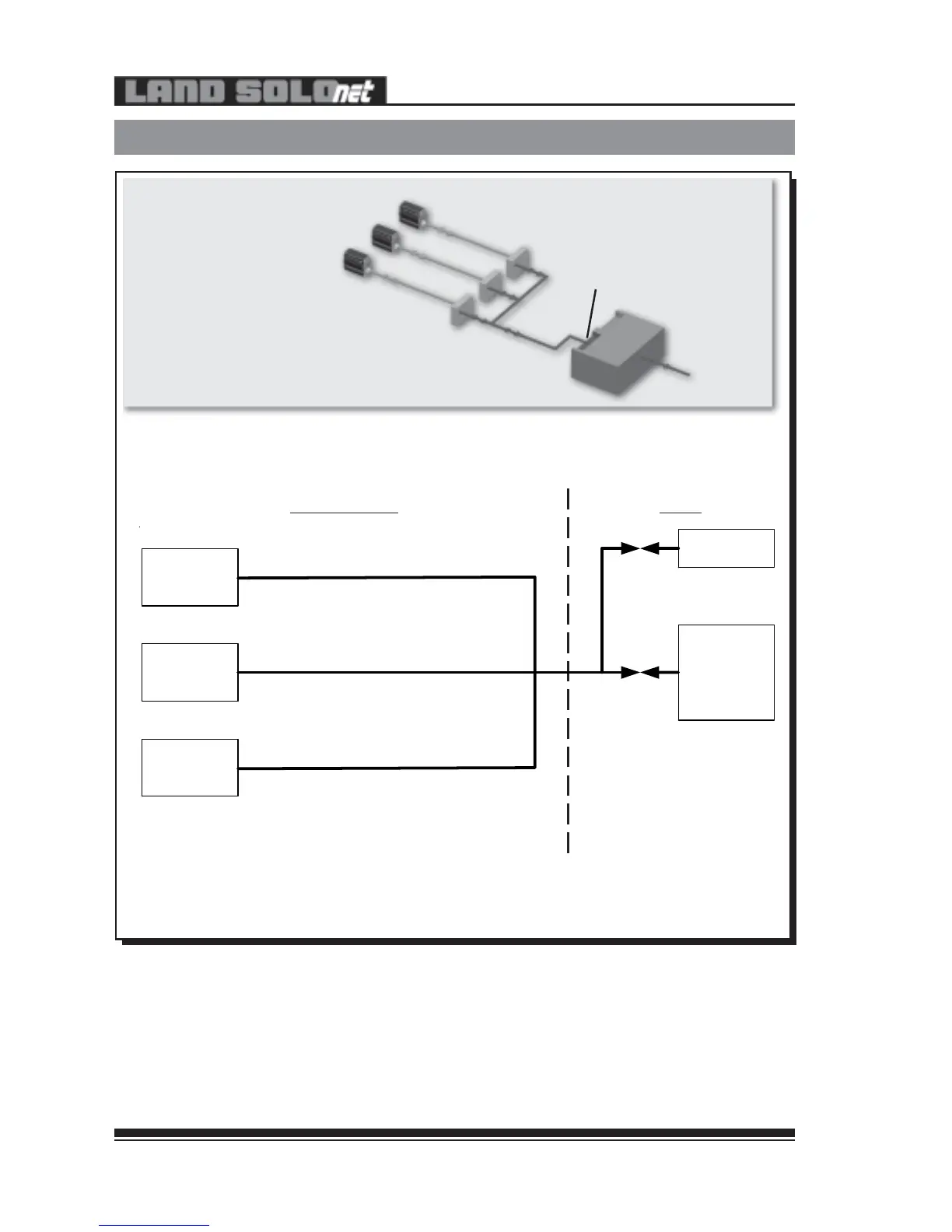
Fig. 15 - Typical RS485 (Non-Ethernet) Installation
Fig. 16 - Schematic Diagram for a Typical RS485
(Non-Ethernet) Installation
307016
SOLOnet SYSTEM PLANT
SOLOnet
Thermometer
RS485
SOLOnet
Thermometer
SOLOnet
Thermometer
RS485
RS485
Digital PLC
Laptop/PC for
Monitoring
Configuration
This application can accommodate single or multiple SOLOnet Thermometers
SOLOnet Thermometers
Customer Terminal Array
SOLOnet Cables
RS485 Link
Digital PLC
PLC RS485 Port
307015
The Current and Contact-closure I/O and RS485 schemes may be combined
and used simultaneously if required.
5.2 Typical RS485 (Non-Ethernet) Installation
Fig. 15 - Typical RS485 (Non-Ethernet) Installation
Fig. 16 - Schematic Diagram for a Typical RS485
(Non-Ethernet) Installation
307016
SOLOnet SYSTEM PLANT
SOLOnet
Thermometer
RS485
SOLOnet
Thermometer
SOLOnet
Thermometer
RS485
RS485
Digital PLC
Laptop/PC for
Monitoring
Configuration
This application can accommodate single or multiple SOLOnet Thermometers
SOLOnet Thermometers
Customer Terminal Array
SOLOnet Cables
RS485 Link
Digital PLC
PLC RS485 Port
307015


 To Next Page