User Guide User Guide
Page 20 Page 20
Fibroptic Thermometer
Fibroptic Thermometer
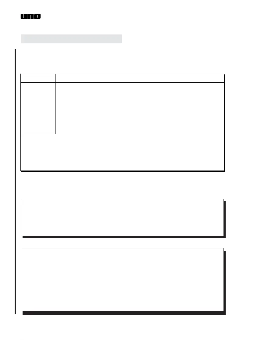
3.7.1 Cable connection schedule
UNO thermometers can be connected, via the 6-way socket, to any compatible
power supply and display equipment. A description of the required connections
is given in the cable connection schedule, Fig. 15.
WARNING
Do not connect either the thermometer output or the command
input to the power supply rails (V+, V-) as this is likely to
damage the thermometer.
If the wiring scheme illustrated in Fig. 16 is not followed, the
thermometer is likely to be damaged. If in doubt, please
contact Land Infrared for advice.
Yellow
Blue
White
Screen
Red
Black
Green
FunctionCable Colour
4 to 20mA linear temperature signal drive
4 to 20mA linear temperature signal return
CMD (Command) input
Screen
23 to 48V, <200mA, dc power (positive)
23 to 48V, <200mA, dc power (negative)
CMD (Command) input
Recommended output load resistance:
Maxim um output load resistance:
CMD (Comm and) input:
100
Ω
400
Ω
Voltage-free switch closure
Switch open = PEAK PICK
Switch closed = TRACK ( or RESET)
NOTE
The screen is connected to the thermometer case. The case
must be grounded at the installation using your preferred
method.
Fig. 15 UNO thermometer cable connection schedule
UN970320
 Loading...