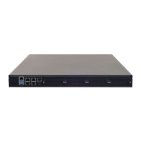
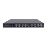
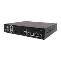
Chapter 2: Hardware Installation
26
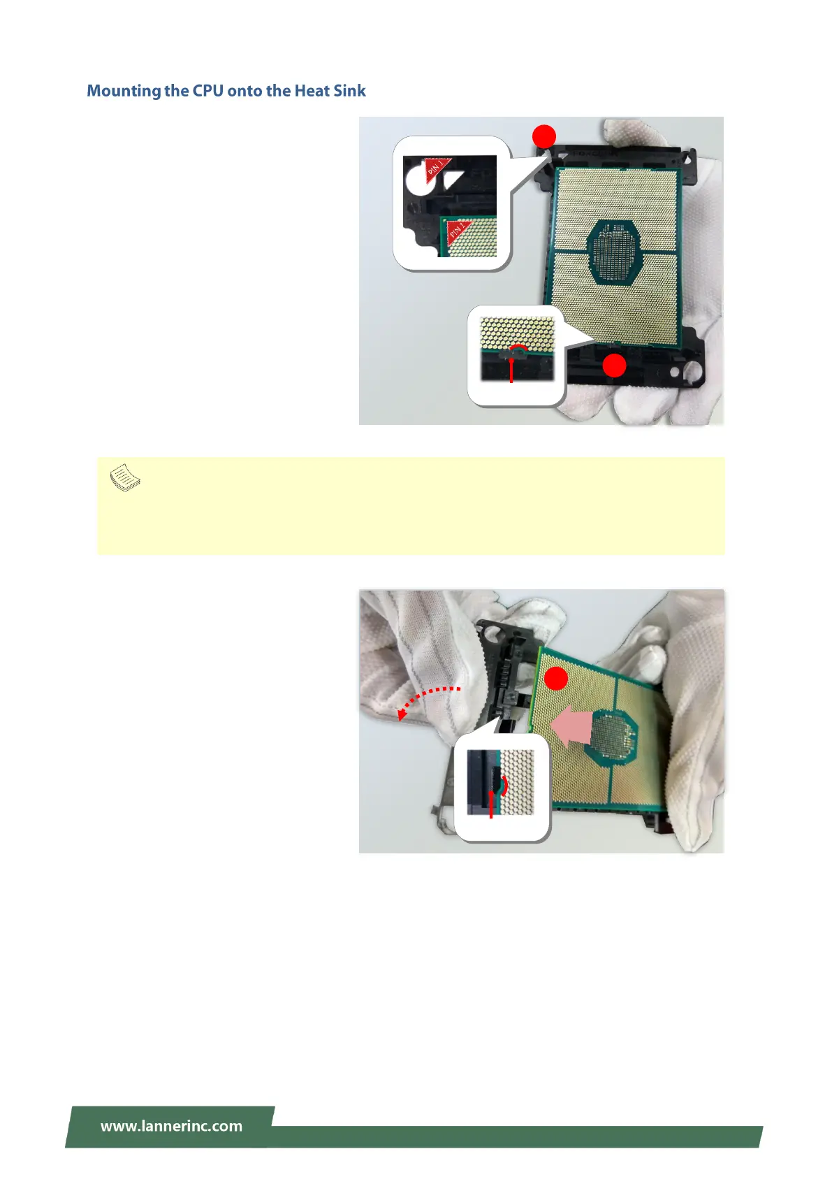
1. Align the PIN1 indicator on the
processor with that on the carrier.
2. Gently insert one side of the
processor into the carrier and make
sure the alignment feature is aligned
with the latch of the carrier.
3. For the other end of the carrier, align
the alignment feature of the
processor with the carrier latch, and
then gently bend over the carrier end
to have the latch secured on the
processor.
Align the
golden
fingers to
the PCIe
socket on
the
motherboa
rd carefully
while
inserting
this
module.
Align the
golden
fingers to
the PCIe
socket on
the
motherboa
rd carefully
while
inserting
this
module.
Note
During assembly, it is essential to have (1) PIN1 on the processor aligned with that on the carrier,
and (2) the alignment features on the top and the bottom of the CPU aligned with the
corresponding carrier latches.