EASE1000 User’s Manual
Chapter 2 General Description
2.5.1 Target System Circuit Configuration
This section describes the circuit configuration of the target system which is necessary to connect a target LSI with
EASE1000.
A pin used to connect a target LSI with EASE1000 is different depending on the specifications of the target LSI. Use
an appropriate pin according to the LSI user's manual.
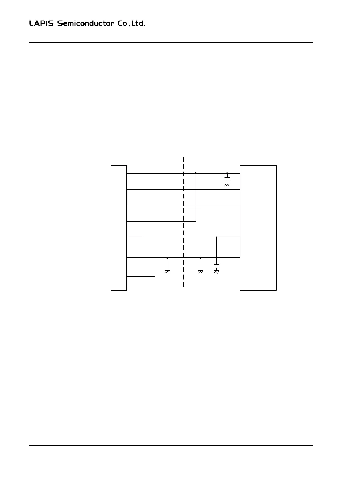
2.5.1.1 ML62Q1000 series is connected as target LSI
The example of a circuit connected with EASE1000 using RESET_N pin and P00/TEST0 pin is shown below.
EASE1000
interface
VTref
RST_OUT/SCK
1
5
SDATA
7
3.3VOUT
13
NC
Vss
2,4,6,8,10,12
3,11,
14
~
VDD
RESET_
N
P00/TEST0
Vss
Target LSI
VDDL
9
VDDL
~
Figure 2-4
Recommended circuitry using RESET_N pin and P00/TEST0 pin
- Do not connect the parts which RESET_N pin is fixed to a High level.
The pull-up resistance is connectable with RESET_N pin.
- When using P00/TEST0 pin, be sure to set P00 as an input mode by a application program.
If P00 is set as an output mode, it becomes impossible to use EASE1000.
FEXTEASE1000-02 6