EASE1000 User’s Manual
Chapter 4 FUNCTIONS
4 Functions
4.1 On-chip debug function
Connecting EASE1000 with a target LSI and using the DTU8 debugger provides the on-chip debug function.
・ Application program download/display/change
・ CPU status (register, Flash memory/Data memory, SFR) display/change
・ Emulation (real time emulation function, step emulation function)
・ Various Break
4.2 Flash writer function
Connecting EASE1000 with a target LSI and using the MWU16 flash multi writer host program provides the flash
writer function.
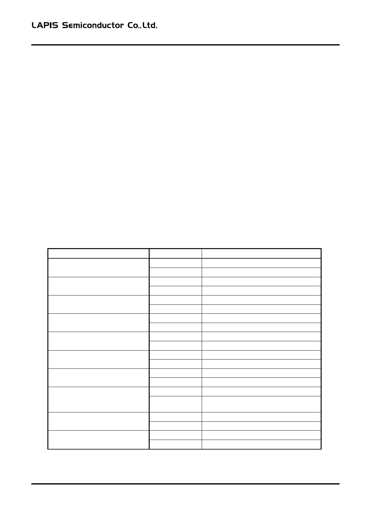
4.3 Indicator
The indicator mounted on EASE1000 notifies of the EASE1000 status.
The following shows the relationship between the EASE1000 state and indicator light state.
Table 4-1 Relationship Table between EASE1000 State and Indicator Light State
Blink (Approximately 0.25-second interval)
VTref abnormal voltage detection
Blink (Approximately 0.5-second interval)
Device driver recognition failure
Blink (Approximately 0.5-second interval)
Blink (Approximately 0.5-second interval)
Blink (Approximately 0.5-second interval)
Communication error with target LSI
Blink (Approximately 0.5-second interval)
Blink (Approximately 0.5-second interval,
reversed)
Blink (Approximately 0.25-second interval)
Blink (Approximately 0.25-second interval)
The following describes the above EASE1000 states.
FEXTEASE1000-02 1