MIPI D-PHY Bandwidth Matrix Table
User Guide
© 2015-2018 Lattice Semiconductor Corp. All Lattice trademarks, registered trademarks, patents, and disclaimers are as listed at www.latticesemi.com/legal.
All other brand or product names are trademarks or registered trademarks of their respective holders. The specifications and information herein are subject to change without notice.
6 FPGA-UG-02041-1.1
2. Video Format
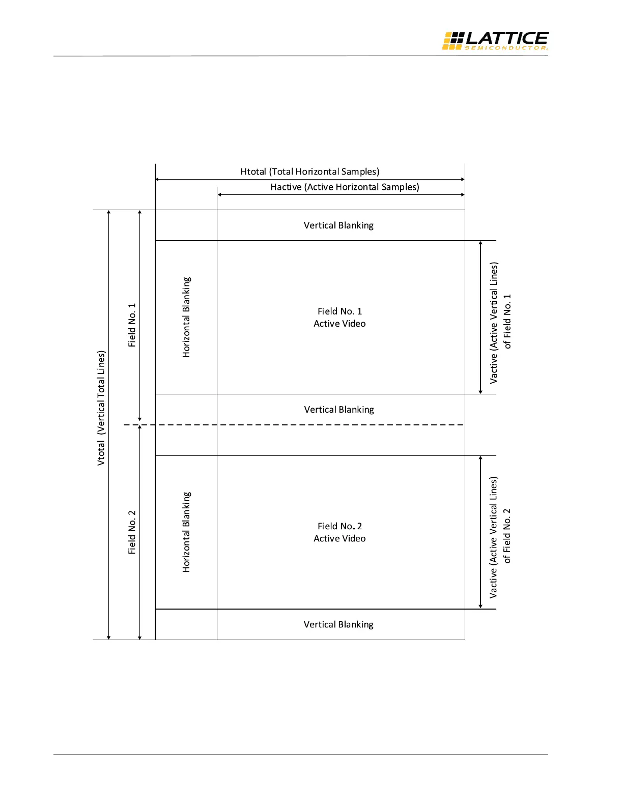
To estimate the data transfer rate, we need to understand the format of the video data transferred over the sensor
bridge. Video is composed of a series of still images. Each still image is composed of individual lines of pixel data. Figure
2.1 illustrates a conceptual interlaced video frame. The progressive video frame is similar to it except for only one field
per frame.
Figure 2.1. Interlaced Mode Video Frame Format
For digital video, either a separate Horizontal Sync (HS), Vertical Sync (VS) and Data Enable (DE) signals are used to
synchronize the video data transfer, or a special sequence embedded into the video data stream indicating the Start of
Active Video (SAV) or End of Active Video (EAV). For MIPI CSI-2, two packets structures are defined for Low Level
Protocol layer: Long packets to carry payload data, and the Short Packets for Frame Synchronization (that is Frame
Start and Frame End) and Line Synchronization (that is Line Start and Line End).
 Loading...