LAUNCH X-431IV English User’s Manual
4
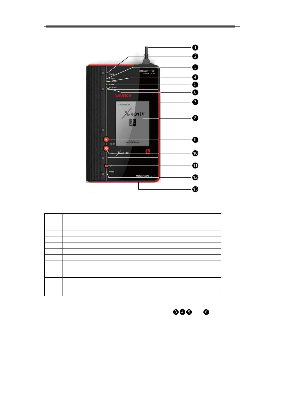
2.1.2 Components Sketch
Figure 2-2 X-431IV structure view (Front)
Table 2-1 formulates all keys, ports and indicators of X-431IV front panel.
Diagnostic connector (Rotatable)
3
Indicator to show SMARTBOX sending data to the main unit
4
Indicator to show SMARTBOX receiving data from the main unit
5
Indicator to show SMARTBOX sending data to ECU
6
Indicator to show SMARTBOX receiving data from ECU
11
Printer LF buttonpaper feed
13
Paper out (printed the data)
Check and identify working states and defeat point of X-431IV by means of the 4 indicators on the
SMARTBOX: There are 4 working state indicators on the SMARTBOX:
, , and (see figure 2-2),
their functions are described respectively as above. It’s necessary to check and identify communications