EasyManua.ls Logo

Launch X431 Scopebox User Manual

Launch X431 Scopebox
113 pages
To Next Page IconTo Next Page
Page #1 background imageLoading...
Page #1 background image
LAUNCH X431 PAD Scopebox User’s Manual
Precaution on Operation
z The appliance is a sophisticated electronic device, never have it clashed
when in use.
z Main unit screen may flash at the moment of engine ignition, which is
normal.
z You may unplug the main unit if the program can not be actuated or
confused screen occurs. Plug again to continue the operation.
z Make sure the appliance is properly connected to the DLC to avoid
communication interruptions.
z During operation, keep the screen upward and leveled.
z Be careful when plugging and unplugging the main cable and diagnostic
connector. Tighten the screw before operation to avoid unexpected
disconnecting and/or damage to the port.
z Handle with care. Avoid collision. Unplug the power after operation.
z After the operation, the stylus shall be inserted into the slot on the main
unit, and put away the cable and connector, etc accessories to the box to
avoid the lost.
z Unplug the power cable by holding the connector, not the cable itself.
Question and Answer IconNeed help?

Do you have a question about the Launch X431 Scopebox and is the answer not in the manual?

Launch X431 Scopebox Specifications

General IconGeneral
Input Voltage12V DC
Channels4
Sampling Rate1GSa/s
Vertical Resolution8-bit
Input Impedance1 MΩ
Voltage Range±40V
ConnectivityBluetooth, USB
Operating SystemAndroid
ProcessorQuad-core
Supported ProtocolsCAN, LIN, FlexRay

Summary

Precaution on Operation

1 Foreword

1.1 Introductions

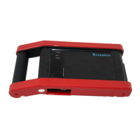
Overview of the X-431 PAD Scopebox and its capabilities.

1.2 Product Features

Highlights key functionalities like rapid signal capture and waveform storage.

1.3 Product Function

Describes the specialized automotive oscilloscope and ignition waveform analysis functions.

1.4 Technical Parameters

Details the specifications such as channels, sampling frequency, and resolution.

2 Structure and Accessories

2.1 Scopebox Structure

Diagram and description of the physical components and ports of the Scopebox.

2.2 Scopebox Accessories

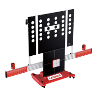
Lists and describes the various accessories included with the Scopebox.

3 Automotive Oscilloscope

3.1 Connection

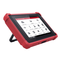
Instructions on how to connect the Scopebox to the main unit and power supply.

3.2 Initial Interface Introduction

Overview of the initial screen layout and graphical elements of the oscilloscope.

3.3 Operations

Detailed procedures for using the oscilloscope functions.

3.3.1 Channel Selection and Attributes Setting

How to select channels and adjust their display and measurement attributes.

3.3.2 Trigger Setting

Configuration of trigger modes, sources, and slopes for waveform capture.

3.3.3 Auto Calibration

Process for calibrating the oscilloscope's vertical and horizontal systems.

3.3.4 Display Settings

Options for adjusting waveform display type (vectors/dots) and grid visibility.

3.3.5 Channel and Cursor Measurement

Methods for measuring signals using channels and cursors for analysis.

3.3.6 File Management

Features for recording, saving, and managing waveform data.

3.3.7 View Software Version

How to check the current software version of the oscilloscope.

3.3.8 Exit Application

Procedure to properly close the oscilloscope application.

4 Automotive Ignition Waveform

4.1 Secondary-Distributor Ignition Analysis

Detailed steps for analyzing secondary-distributor ignition waveforms.

4.2 Secondary-Simultaneous Ignition Analysis

Procedure for analyzing secondary-simultaneous ignition waveforms.

4.3 Secondary-Direct Ignition Analysis

Steps for analyzing secondary-direct ignition waveforms.

4.4 Waveform Analysis Mode

Explains the main uses of single-cylinder waveform testing for engine diagnostics.

Related product manuals