EasyManua.ls Logo

Launch X-431 EURO TAB II User Manual

Launch X-431 EURO TAB II
150 pages
To Next Page IconTo Next Page
Page #1 background imageLoading...
Page #1 background image
X-431 EURO TAB II User Manual
i
Important Safety Precautions
Important: To avoid personal injury, property damage, or accidental damage to
the product, read all of the information in this section before using the product.
 Never collide, throw, or puncture the tool, and avoid falling, extruding and
bending it.
 Do not insert foreign objects into or place heavy objects on your device.
Sensitive components inside might cause damage.
 Do not use the tool in exceptionally cold or hot, dusty, damp or dry
environments.
 In places using the tool may cause interference or generate a potential risk,
please turn it off.
 This tool is a sealed unit. There are no end-user serviceable parts inside. All
internal repairs must be done by an authorized repair facility or qualified
technician. If there is any inquiry, please contact the dealer.
 Never place the tool into apparatus with strong electromagnetic field.
 Keep the tool far away from magnetic devices because its radiations can
damage the screen and erase the data stored on the tool.
 DANGER: Do not attempt to replace the internal rechargeable lithium battery.
Contact the dealer for factory replacement.
 CAUTION: Please use the included battery and charger. Risk of explosion if
the battery is replaced with an incorrect type.
Precautions on Using This Tool
Before using this tool, please read the following safety information carefully.
 Always perform automotive testing in a safe environment.
 If the VCI (Vehicle Communication Interface) device is not in use for a long
period of time, it is suggested to unplug the connector from vehicle’s DLC to
conserve battery power.
 Wear an ANSI-approved eye shield when testing or repairing vehicles.
 The vehicle shall be tested in a well-ventilated work area, as engines produce
various poisonous compounds (hydrocarbon, carbon monoxide, nitrogen
oxides, etc.)
 Do not connect or disconnect any test equipment while the ignition is on or
the engine is running.
 Put blocks in front of the drive wheels and never leave the vehicle unattended
(c) Launch & Diagtools. Tel. +37167704152, +37129416069. www.diagtools.lv
Diagtools

Table of Contents

Question and Answer IconNeed help?

Do you have a question about the Launch X-431 EURO TAB II and is the answer not in the manual?

Launch X-431 EURO TAB II Specifications

General IconGeneral
RAM4 GB
Internal Storage64 GB
Resolution1920 x 1200 pixels
Processor2.0 GHz Octa-core
Expandable StorageUp to 128 GB via microSD
Display10.1 inches
Operating SystemAndroid
Camera2MP front
ConnectivityWi-Fi, Bluetooth
Supported ProtocolsCAN, J1850, ISO9141, KWP2000

Summary

Important Safety Precautions

Precautions on Using This Tool

Safety guidelines for operating the diagnostic tool, covering environment and user conduct.

Precautions on Operating Vehicle’s ECU

5 DIAGNOSIS

5.1 INTELLIGENT DIAGNOSIS

Automated vehicle diagnosis using VIN to access cloud data and history.

5.2 LOCAL DIAGNOSIS

Manual vehicle diagnosis procedures and system selection.

5.3 REMOTE DIAGNOSIS

Enables remote assistance and diagnosis between users or with technicians.

6 SPECIAL (RESET) FUNCTION (ONLY FOR PASSENGER VEHICLE/GASOLINE & DIESEL VERSION)

6.1 OIL RESET SERVICE

Resets the engine oil life system after maintenance or oil change.

6.2 ELECTRONIC PARKING BRAKE RESET

Resets the electronic parking brake system after brake pad replacement.

8 ADAS

9 SENSORBOX (TOOLBOX)

9.1 Product Summary

Overview of the Sensorbox module for sensor simulation and multimeter tests.

9.2 Structure & Accessories

Details on the Sensorbox structure and its accessories.

9.3 Sensor Simulation

Performing various sensor simulation tests.

10 MULTIMETER (TOOLBOX)

11 BATTERYBOX (TOOLBOX)

11.1 Product Summary

Overview of the Batterybox module for vehicle battery testing.

11.2 Test Environment

Details on inside and outside vehicle testing environments.

11.3 Batterybox Structure & Accessories

Structure and accessories of the Batterybox module.

11.4 Connections & Operations

Guides on connecting and operating the Batterybox module.

11.5 Precautions On Battery Test

Important precautions for accurate battery testing results.

12 OSCILLOSCOPE (TOOLBOX)

12.1 Introduction

Overview of the oscilloscope module and its capabilities.

12.2 Structure & Accessories

Structure and accessories of the Scopebox module.

12.3 Connection & Initial Use

Steps for connecting and initial setup of the oscilloscope.

12.4 Operations

Guide to operating the oscilloscope functions and settings.

13 AUTOMOTIVE IGNITION WAVEFORM (TOOLBOX)

13.1 Secondary-distributor ignition analysis

Analyzing secondary-distributor ignition waveforms.

13.2 Secondary-simultaneous ignition analysis

Analyzing secondary-simultaneous ignition waveforms.

13.3 Secondary-direct ignition analysis

Analyzing secondary-direct ignition waveforms.

13.4 Waveform analysis mode

Modes for analyzing ignition waveforms.

14 USER INFO

14.1 My Report

Management of saved diagnostic reports and files.

1 Introduction

1.1 Product Profile

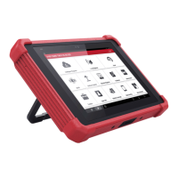
Overview of the X-431 EURO TAB II tablet's features and capabilities.

1.2 Features

Detailed description of the diagnostic tool's key features and functions.

1.3 Technical Specifications

1.3.1 Display tablet

Technical specifications for the display tablet component.

1.3.2 VCI device

2 Knowledge of X-431 EURO TAB II

2.1 DISPLAY TABLET

Detailed information and diagram of the display tablet.

2.2 DOCKING STATION (OPTIONAL)

Information about the optional docking station.

2.3 VCI DEVICE

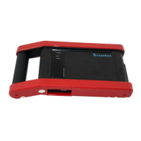
Detailed information and diagram of the VCI device.

2.2 Docking Station (Optional)

2.3 VCI Device

2.3 Package List

3 Initial Setup

3.1 Charging The Tablet

Instructions for charging the tablet using the provided power adaptor.

3.2 Power On/Off

Steps to power the tablet on and off.

3.3 Screen Layout

Description of the tablet's on-screen keys and status bar.

3.4 Adjusting Screen Brightness

3.5 Changing Language

3.6 Network Setup

4 Getting Started

4.1 Diagnostic Flowchart

Flowchart illustrating the initial steps for using the diagnostic tool.

4.2 Register & Download Diagnostic Software

Process for registering the device and downloading diagnostic software.

4.2.1 User registration

Steps for creating a user account and registering the device.

4.2.2 Home screen

5 DIAGNOSIS

Intelligent Diagnose

Automated diagnosis using VIN for quick vehicle data retrieval.

Local Diagnose

Manual diagnosis by selecting vehicle and system.

Reset

Performs common maintenance and reset functions for vehicles.

ADAS

Provides access to ADAS calibration functions.

Software Update

Updates diagnostic software and application.

Remote Diagnose

Facilitates remote diagnosis and instant messaging.

Feedback

Allows submitting diagnostic logs for analysis and troubleshooting.

Maintenance

Access to maintenance data for vehicle diagnosis and repair.

Toolbox

Includes various diagnostic tools like Camera, Browser, Oscilloscope.

User Info

Manages VCI, reports, password, and settings.

Vehicle Coverage

Tablet Setting

Other Modules

4.2.3 Vehicle menu layout

4.2.4 Diagnostics toolbar

4.3 Diagnosis Methods

4.4 Connections

4.4.1 Preparation

Pre-diagnosis checks and conditions.

4.4.2 DLC location

Information on locating the Data Link Connector (DLC) on vehicles.

4.4.3 Vehicle connection (For Passenger Vehicle Version)

4.4.3 Vehicle connection (For Commercial Vehicle/ Gasoline & Diesel Version)

5 Diagnosis

5.1 Intelligent Diagnosis

Guides through automatic VIN scan and vehicle information retrieval.

5.2 Local Diagnosis

VIN Scan

INPUT VIN

B) Manual Selection

Select diagnostic software version

Choosing the appropriate software version for diagnosis.

5.2.1 Health Report (Quick Test)

C. Clear Fault Code

D. Read Data Stream

Display Modes

Compare Sample

Record

Save Sample

E. Actuation Test

5.3 Remote Diagnosis

5.3.1 Interface layout

Overview of the remote diagnosis interface.

5.3.2 Add friends

5.3.3 Start instant messaging

5.3.4 Launch remote diagnosis (Device-To-Device)

Send remote diagnostic reservation

Reserving a remote diagnosis session.

Request control remote device

Requesting remote control of a partner's device.

Invite remote diagnostic assistant

Inviting a technician for remote assistance on your tool.

5.3.5 Launch remote diagnosis (Device-To-PC)

5.4 How to View Diagnostic History?

5.5 How to Feedback Diagnostic Logs?

6 Special (Reset) Function (Only for Passenger Vehicle/Gasoline & Diesel Version)

Oil Reset Service

Resets the engine oil life system.

Electronic Parking Brake Reset

Resets the electronic parking brake system.

Steering Angle Calibration

Resets the steering angle sensor.

ABS Bleeding

Performs ABS bleeding to restore brake sensitivity.

TPMS (Tire Pressure Monitor System) Reset

Resets the Tire Pressure Monitoring System.

Gear Learning

Performs crankshaft position sensor learning.

IMMO Service

Anti-theft key matching for immobilizer systems.

Injector Coding

Codes injectors to ECU for accurate fuel injection.

Battery Maintenance System

Resets battery monitoring unit and performs battery matching.

Diesel Particulate Filter (DPF) Regeneration

Clears Particulate Matter (PM) from DPF filter.

Electronic Throttle Position Reset

Resets throttle actuators to default values.

Gearbox Matching

Completes gearbox self-learning for improved shifting.

AFS (Adaptive Front-lighting System) Reset

Initializes the adaptive headlamp system.

Sunroof Initialization

Sets sunroof memory functions and thresholds.

Suspension Calibration

Adjusts body height sensor for air suspension calibration.

6.1 Oil Reset Service

6.2 Electronic Parking Brake Reset

6.3 Steering Angle Calibration

6.4 ABS Bleeding

6.5 Tire Pressure Monitor System Reset

6.6 Gear Learning

6.7 IMMO Service

6.8 Injector Coding

6.9 Battery Maintenance System Reset

6.10 Diesel Particulate Filter (DPF) Regeneration

6.11 Electronic Throttle Position Reset

6.12 Gearbox Matching

6.13 AFS (Adaptive Front-lighting System) Reset

6.14 Sunroof Initialization

6.15 Suspension Calibration

7 Software Update

7.1 Update Diagnostic Software & APP

Updates diagnostic software and applications.

7.2 Set Frequently Used software

Creates a list of frequently used software for quick access.

7.3 Renew Subscription

8 ADAS

ADAS Activation

Steps to activate the ADAS calibration function using a password.

9 Sensorbox (Toolbox)

9.1 Product Summary

Overview of the Sensorbox module for sensor simulation and multimeter tests.

9.2 Structure & Accessories

Details on the Sensorbox structure and its accessories.

9.3 Sensor Simulation

Performing various sensor simulation tests.

9.2.1 Sensorbox structure

9.2.2 Sensorbox accessories

9.3.1 Connections

9.3.2 Simulation test

1. DC voltage simulation

2. Fixed frequency simulation

3. Predefined waveform simulation

4. Hand-painted waveform simulation

9.3.3 Precautions on checking vehicle sensor

10 Multimeter (Toolbox)

10.1 Main Menu

Accessing the multimeter test menu after connecting the Sensorbox.

10.2 Test Sample

11 Batterybox (Toolbox)

11.1 Product Summary

Overview of the Batterybox module for vehicle battery testing.

11.2 Test Environment

Details on inside and outside vehicle testing environments.

11.2.2 Battery status and description

Explanation of different battery states and their meanings.

11.3 Batterybox Structure & Accessories

11.3.1 Batterybox structure

Diagram and description of the Batterybox ports and indicators.

11.3.2 Test accessories

List of accessories for the Batterybox module.

11.4.1 Connection

11.4.2 Inside the vehicle test

1. Battery test

Procedure for conducting battery tests inside the vehicle.

2. Charging system and starting system test

11.4.3 Outside the vehicle test

11.5 Precautions On Battery Test

12 Oscilloscope (Toolbox)

12.1 Introduction

Overview of the oscilloscope module and its capabilities.

12.2 Structure & Accessories

12.2.1 Scopebox structure

Diagram and description of the Scopebox ports and indicators.

12.2.2 Scopebox accessories

List of accessories for the Scopebox module.

12.3.1 Probe Compensation

12.3.2 Connection

A. While testing sensors or actuators,

Connection setup for testing sensors and actuators.

C. While testing Secondary-direct ignition analysis,

12.3.3 Initial interface introduction

12.4 Operations

12.4.1 Channel selection and attributes setting

Selecting channels and setting attributes like Time/DIV and Volts/DIV.

<2> Channel attributes & trigger setting

Trigger setting

1) If Edge trigger is selected

2) If Pulse Width trigger is selected

12.4.2 Auto

12.4.3 View Settings

<1> Calibration

Calibrating the Scopebox's vertical and horizontal systems.

<2> REF settings

<3> Display settings

12.4.4 Measure

<1> Channel source

Selecting the source channel for measurements.

<2> Horizontal / Vertical measure

<3> Clear measure

12.4.5 File management

<1> Save snapshot

Saving the current screen as a snapshot.

<2> Snapshot manager

Managing saved snapshots (view, delete, edit).

<3> Record waveform

Recording and saving waveforms for future recall.

<4> Load waveform for playback

12.4.6 Expert reference

<1> Expert Reference

Using saved waveforms as references for comparison.

<2> Base Reference

13 Automotive Ignition waveform (Toolbox)

13.1 Secondary-distributor ignition analysis

Analyzing secondary-distributor ignition waveforms.

13.2 Secondary-simultaneous ignition analysis

13.3 Secondary-direct ignition analysis

13.4 Waveform analysis mode

14 User Info

14.1 My Report

Viewing, deleting, and sharing saved diagnostic reports.

Diagnostic Record

14.2 VCI

14.3 Activate VCI

14.4 Fix Connector Firmware/System

14.5 My News

14.6 Data Stream Sample

14.7 Vehicle Voltage

14.8 My Order

14.9 Subscription Renewal Card

14.10 Profile

14.11 Change Password

14.12 Settings

14.12.1 Units

Configuring measurement units (Metric/English).

14.12.2 Shop Information

Defining workshop and print information.

14.12.3 Printer Set

Establishing wireless connection with the mini printer.

14.12.4 Clear Cache

14.12.5 About

14.12.6 Diagnostic Software Auto Update

14.12.7 Login/Exit from current account

14.13 Diagnostic Software Clear

15 Other Modules

15.1 Email

Sending and receiving emails.

15.2 Browser

Launching the web browser for online access.

15.2.1 Open browser

15.2.2 Download files

15.3 TeamViewer

15.3.1 TeamViewer QuickSupport

Requesting remote support from a partner.

15.3.2 TeamViewer

15.4 System OTA Upgrade

15.5 File Explorer

15.6 Synchronization

16 FAQ

Communication error with vehicle ECU?

Troubleshooting steps for communication errors with the vehicle ECU.

Failed to enter into vehicle ECU system?

Troubleshooting steps for failing to enter the vehicle ECU system.

How to save power?

Tips for conserving battery power on the device.

How to reset the tablet?

Warning and procedure for resetting the tablet.

Method 1

Method 2

How to activate new VCI device?

How to update Android?

How to update the APK and diagnostic software?

The diagnostic application is failing.

How to retrieve the login password?

Warranty

Disclaimer

Purchase Order

Customer Service

Statement:

Related product manuals