X-431 EURO TAB II User Manual
84
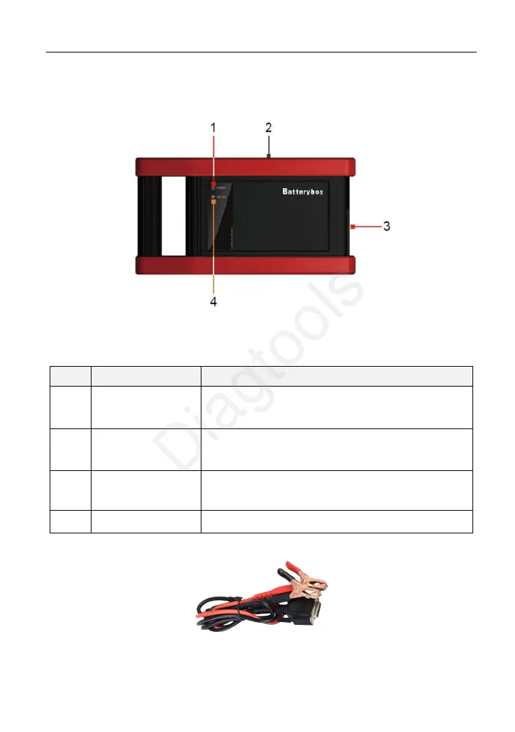
11.3 Batterybox Structure & Accessories
11.3.1 Batterybox structure
Fig.11-1 Batterybox
Below describes the ports and indicators for the Batterybox.
No.
Name Descriptions
1
Power LED
It keeps solid red after the Scopebox is powered
on.
2
B-shaped data
I/O port
Connect to the diagnostic tool via data cable so
that the signal can be displayed on the tool.
3
Battery connector
Connect the Kelvin clip to battery for battery
test.
4
Status LED
11.3.2 Test accessories
Fig. 11-2 Kelvin clip
(c) Launch & Diagtools. Tel. +37167704152, +37129416069. www.diagtools.lv
 Loading...