X-431 EURO TAB II User Manual
85
Fig. 11-3 A/B cable
11.4. Connections & Operations
11.4.1 Connection
Connect one end of the data cable to the B-shaped data I/O port of the
Batterybox, and tighten the captive screws, and then connect the other end to
the data I/O port of the diagnostic tool. This connection applies to outside the
vehicle test and inside the vehicle.
*Notes:
1. Wait about 10 seconds and begin to communicate since the batterybox needs to
initialize after connection is complete, otherwise, communication may fail.
2. Red lamp on the batterybox means it has been successfully powered up; If the
green light is always on, it indicates the clip is well connected; while the green light
blinks, it indicates that the clip has poor contact. Do not perform any test until the
clip and A/B cable are properly connected.
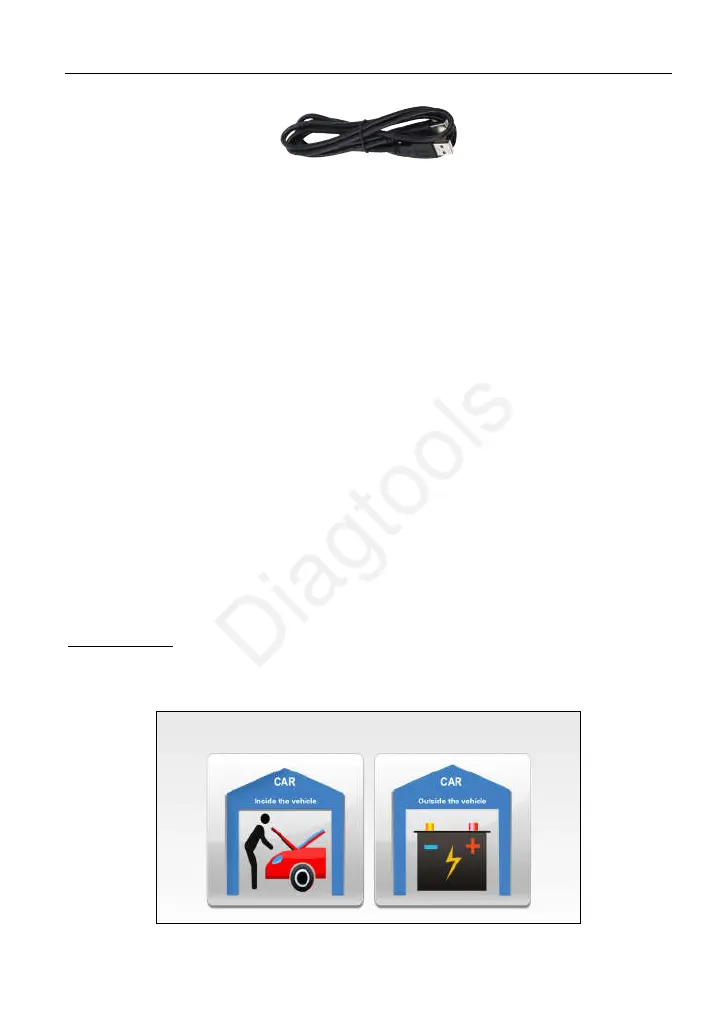
11.4.2 Inside the vehicle test
Battery test and charging system & actuation system test can be done in this
mode.
1. Battery test
Enter battery test main menu, and select a desired test environment as shown in
Fig. 11-4.
Fig. 11-4
(c) Launch & Diagtools. Tel. +37167704152, +37129416069. www.diagtools.lv
 Loading...