X-431 EURO TAB II User Manual
70
Precision ±5%
Voltage test Testing range DC-400V~+400V
Input impedance 10Mohm
Resistance test Testing range 0~40Mohm
Frequency test Testing range 0~25KHz
Input impedance 1000Gohm
Input voltage 1~12V
9.2 Structure & Accessories
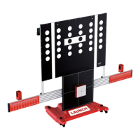
9.2.1 Sensorbox structure
Fig. 9-1 Structural diagram of Sensorbox
Table 9-1 shows the ports and indicators for the sensorbox
No.
Name Description
1
Data receiving LED
Indicator (green) for receiving data from the
diagnostic tool.
2
Data sending LED Indicator (green) for sending data to the
(c) Launch & Diagtools. Tel. +37167704152, +37129416069. www.diagtools.lv
 Loading...