X-431 EURO TAB II User Manual
92
12.2 Structure & Accessories
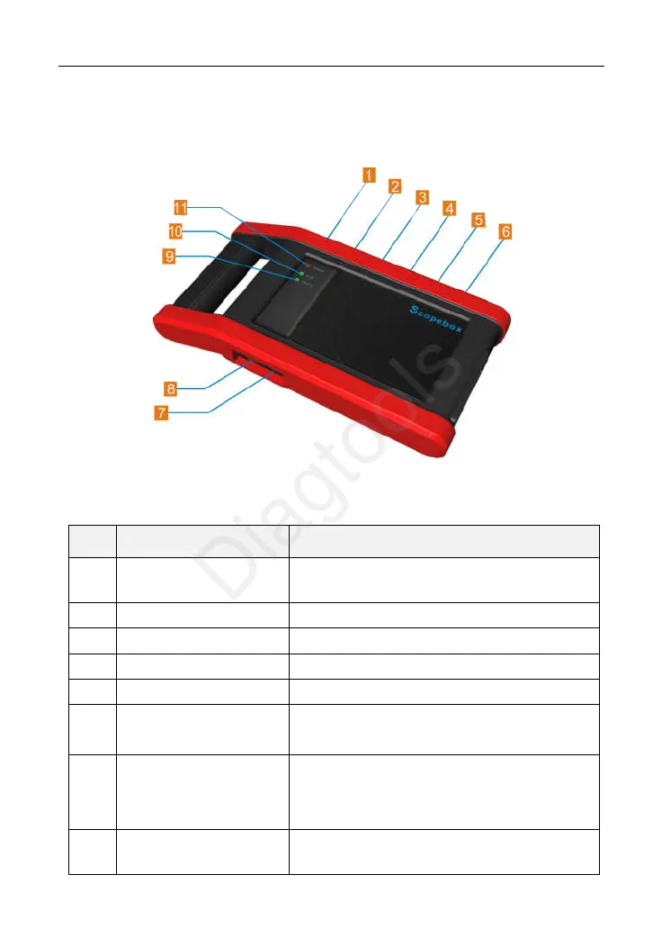
12.2.1 Scopebox structure
Fig 12-1 Scopebox Structure Diagram
Table 12-1 shows the ports and indicators for the Scopebox.
No.
Name Description
1 Fixed signal generator
Generate a square signal with fixed 1K
frequency.
2 CH1 Channel 1
3 CH2 Channel 2
4 CH3 Channel 3
5 CH4 Channel 4
6 External trigger
External trigger signal
Scopebox failed to trigger the signal itself.)
7
B-shaped data I/O
Port
Connect to the diagnostic tool via data
cable so that the signal can be displayed
on the tool.
8 Power interface
To provide power to it via the power
adaptor or battery clamps cable.
(c) Launch & Diagtools. Tel. +37167704152, +37129416069. www.diagtools.lv
 Loading...