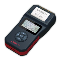
Oscilloscope power indicator, which will
be steady red after the oscilloscope is
powered on
8 Operating
indicator
The indicator will be steady green after
the oscilloscope operated.
9 Communica
indicator
tion After the data communication, the
indicator will blink (Green).
10 Power interface
Connect to power supply via the power
adapter.
11 B-shaped USB
interface
Connect main unit via USB connect line
as separated individual USB devices
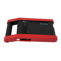
.2 S x acc
kup cable for 4-channel
nel oscilloscope, etc. See
th the product may differ from the accessories listed on
2 copebo essories
Scopebox includes the secondary pic
oscilloscope, crocodile clips for 4-chan
Table 2-2.
As the produc
t configuration can be different, the accessories
included wi
this manual. Please see the packing list attached to the product for
the detailed acc
essories.
 Loading...