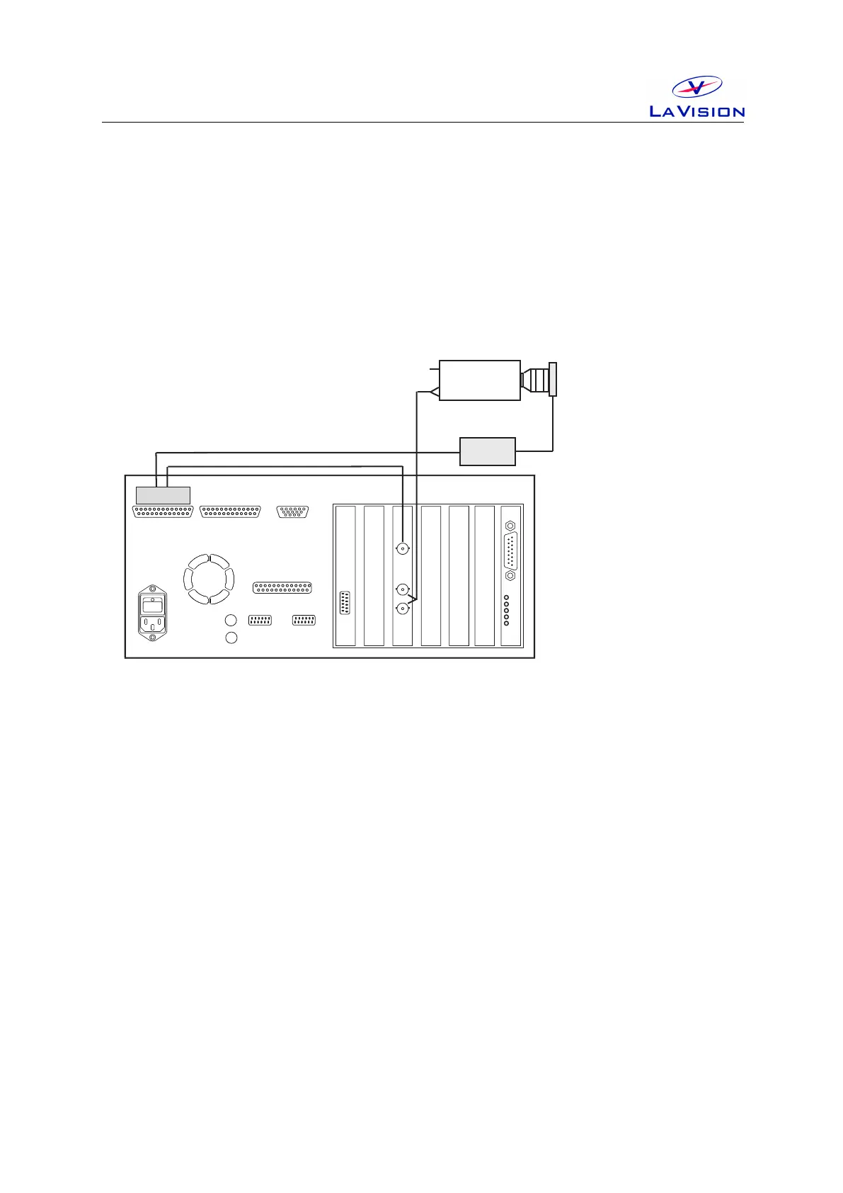
3 Wiring
PTU
Cam1
Network
VGA
Power
Printer Port
COM1
COM2
Camera Cable
(Coax or FOL)
Blue BNC
Mouse
Keyboard
Computer Rear Panel
Camera
PTU Port A
PTU Port B
TTL I/O
Black BNC
Camera 1
Power
Data
Ext. Trig.
ShutterDriver
Camera
Shutter
Figure 3.1: Wiring of camera shutter and driver.
• Connect shutter with driver, plug the cable into the Shutter socket
at the driver front panel and the Lemo connector at the side of the
camera shutter.
• Connect Ext.Trig at the driver front panel with BNC labeled Cam
Shutter(Pin A7) of PTUPortA(Camera connector).
• Connect the driver to 115 V /220 V . Set key switch on rear panel to 1.
• Set the key switch on front panel to Normal.
13