14
Connect launch control 12V wire to pin 2 and “GND” wire to pin 3. Cut one ignition signal wire and
connect the side going to the ECU to CH1 IN and the end going to the coil to CH1 OUT. Do the same
for the other ignition signal wire but connect to CH2 IN and CH2 OUT. Mount the clutch switch and
connect to Launch wire.
Unfortunately, the coil connector is square so it is unclear which pin is 1, 2, 3, 4… So you could
measure the 12V and the Ground wire using a multimeter to make sure. The other 2 wires would be
the ignition signals.
Double ignition coil on top of engine (with 3 pin connector) and
ignitor on the left hand side of the engine bay
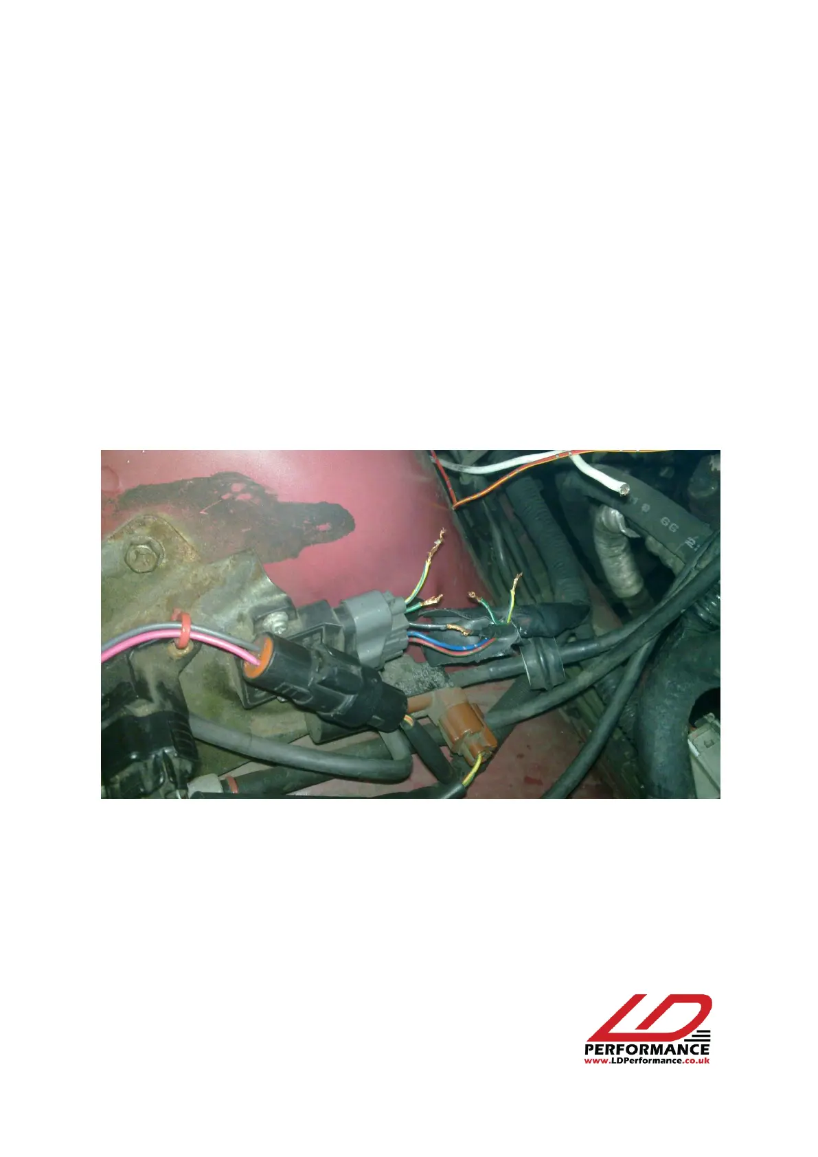
1. Locate the ignition module on the left side of the engine bay and cut the following wires:
There is no need to cut the black one.
Closer view: