6
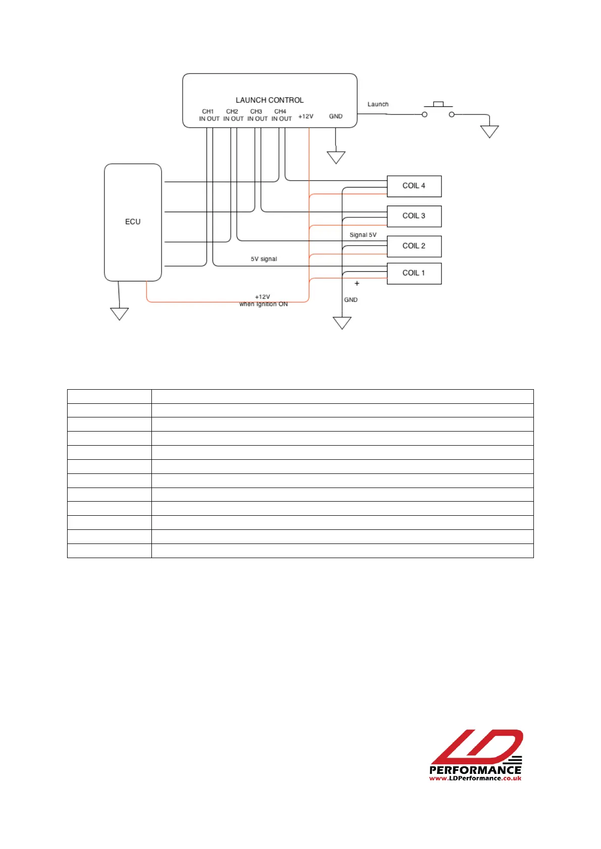
Figure 2: Wiring diagram with amplified coils
All wires to the Launch control module are marked in the following way:
12V ignition “ON” power supply
Signal to ignition module channel 1 / To coil 1 signal wire
Signal to ignition module channel 2 / To coil 2 signal wire
Signal to ignition module channel 3 / To coil 3 signal wire
Signal to ignition module channel 4 / To coil 4 signal wire
Connects to clutch switch – Launch is activated when connected to ground
If the number of coils is less than 4, only the relevant channels are connected; for example, if two
coils are used (or one double coil) leave CH3 IN, CH3 OUT, CH4 IN, CH4 OUT not connected to
anything.