Control and Status Indicator Summary
Tune Button functions:
Short press: Bypass
Medium press: Memory Tune
Long press: Full Tune
Tune attempt, but no RF
LED Indicators:
Green LED flashes
Red LED comes on
Red LED goes off
Red LED flashes
Theory of Operation
Some basic ideas about impedance
The theory underlying antennas and transmission lines is fairly complex, and in fact employs a
mathematical notation called “complex numbers” that have “real” and “imaginary” parts. It is
beyond the scope of this manual to present a tutorial on this subject, but a little background will
help you understand what your Z-100 is doing, and how it does it.
In simple DC circuits, the wire resists the current flow, converting some of it into heat. The
relationship between voltage, current and resistance is described by the elegant and well-known
“Ohm’s Law”, named for Sir George Simon Ohm of England, who first described it in 1826. In
RF circuits, an analogous but far more complicated relationship exists.
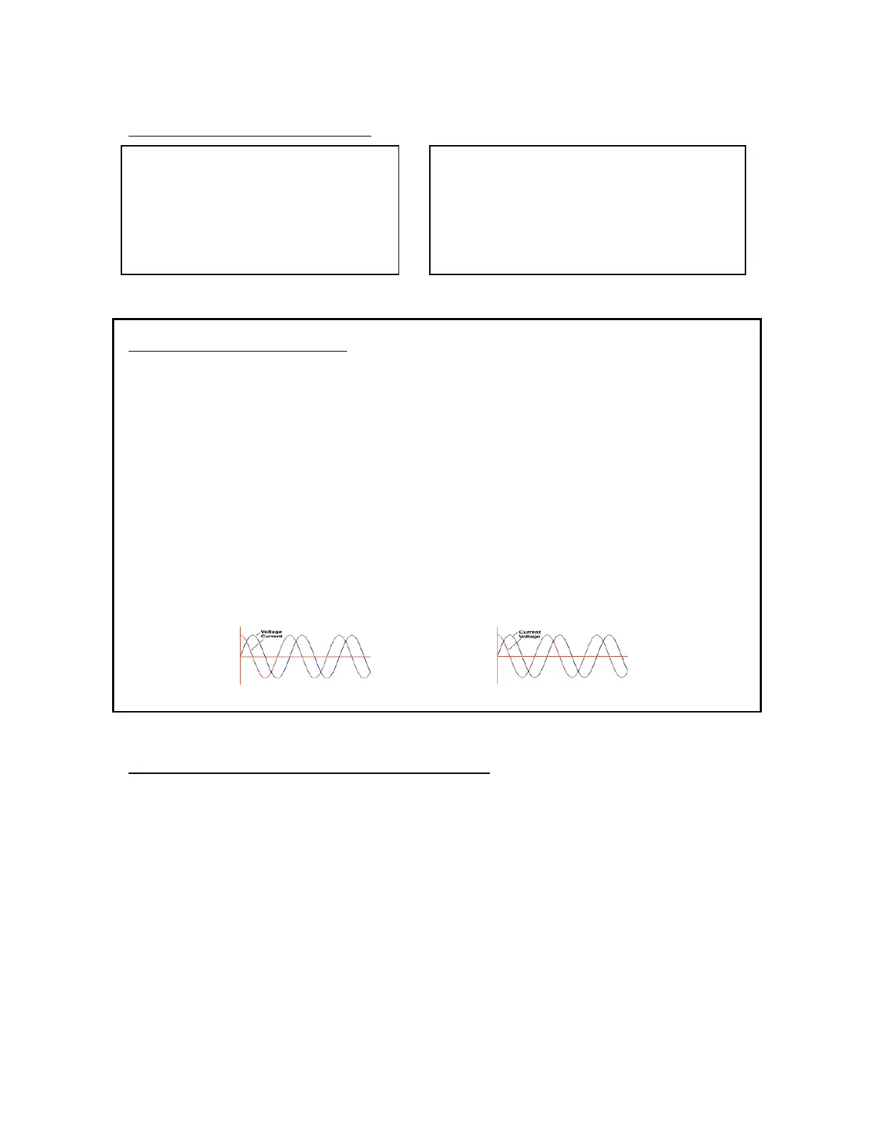
RF circuits also resist the flow of electricity. However, the presence of capacitive and inductive
elements causes the voltage in the circuit to lead or lag the current, respectively. In RF circuits
this resistance to the flow of electricity is called “impedance”, and can include all three elements:
resistive, capacitive, and inductive.
Capacitive
Reactance
Inductive
Reactance
Transmitters, transmission lines, antennas and impedance
The output circuit of your transmitter, the transmission line, and the antenna all have
characteristic impedance. For reasons too complicated to go into here, the standard impedance is
about 50 ohms resistive, with zero capacitive and inductive components. When all three parts of
the system have the same impedance, the system is said to be “matched”, and maximum transfer
of power from the transmitter to the antenna occurs. While the transmitter output circuit and
transmission line are of fixed, carefully designed impedance, the antenna presents a 50-ohm, non-
reactive load only at its natural resonant frequencies. At other frequencies, it will exhibit
capacitive or inductive reactance, causing it to have an impedance different from 50 ohms.
The ratio of transmitted to reflected energy is called the “standing wave ratio”, or SWR. An SWR
of 1 (sometimes written 1:1) indicates a perfect match. As more energy is reflected, the SWR
rises to 2, 3 or higher. As a general rule, modern solid state transmitters must operate with an
SWR of 3 or less. Tube exciters are somewhat more tolerant of high SWR. If your 50-ohm
9
 Loading...