H2-506 Vector Easy Servo Drive User Manual Version 1.0
Leadshine Technology Co., Ltd
11/F, Block A3, iPark, No.1001 Xueyuan Blvd. Shenzhen, China Tel: 1-949-608-7270 Fax: 1-949-608-7298
Web: www.leadshine.com Email: tech@leadshine.com
3 Connectors and Pin Assignments
3.1 Control Signal Connector CN1
CN1 – Control Signal Connector
Enable signal: This signal is used for enabling/disabling the driver. By default, high level
(NPN control signal) for enabling the driver and low level for disabling the driver. It is
usually left UNCONNECTED (ENABLED). Please note that the PNP and Differential
control signals are on the contrary, namely Low level for enabling. The active level of
ENA signal is software configurable.
Pulse signal: In single pulse (pulse/direction) mode, this input represents pulse signal,
each rising or falling edge active (software configurable); In double pulse mode
(software configurable), this input represents clockwise (CW) pulse, active both at high
level and low level. 5-24V when PUL-HIGH, 0-0.5V when PUL-LOW. For reliable
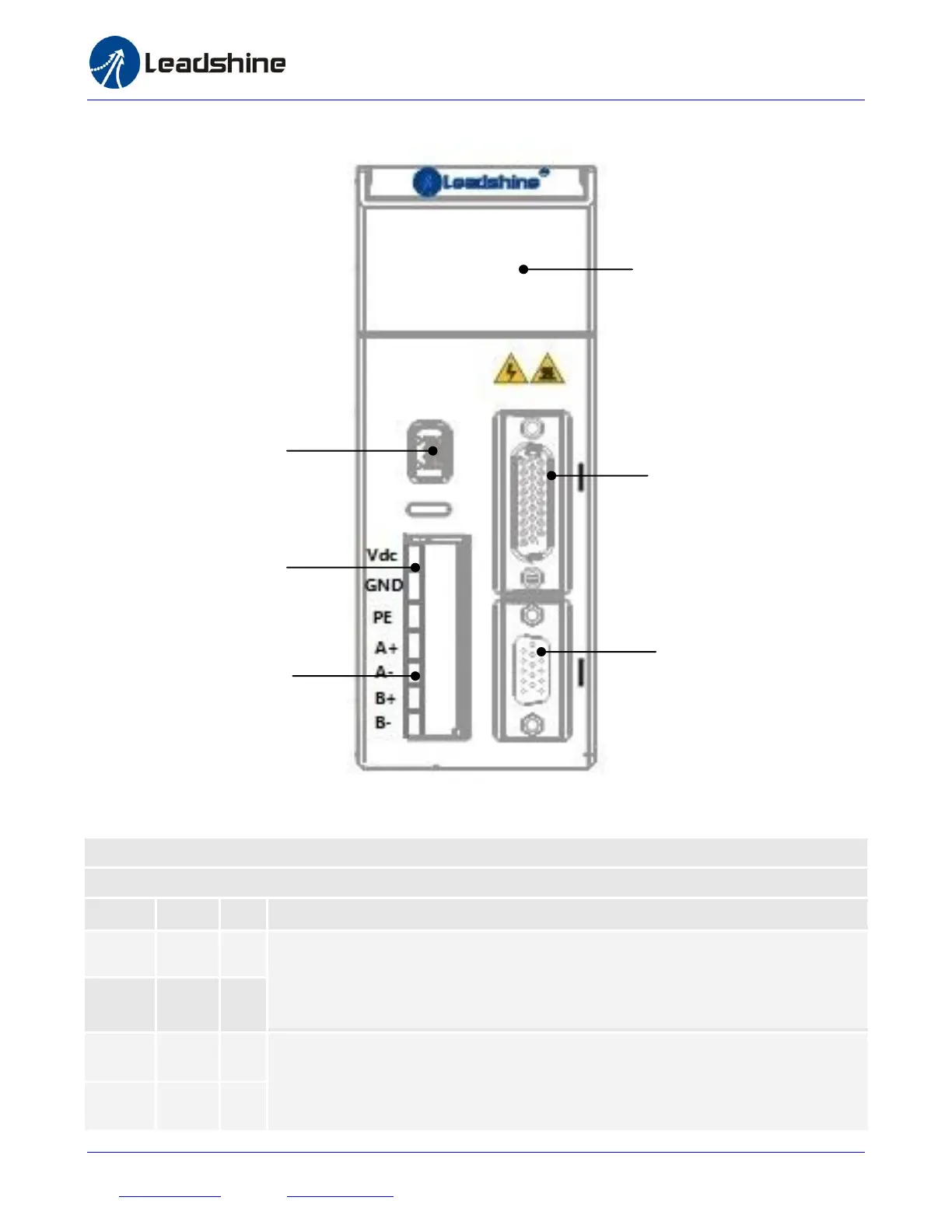
On-board HMI
Self-test,
On-board Configuration
CN3
RS232 Configuration
Port
CN1
Control Signal Connector
Pulse, Direction, Enable Inputs
and Fault and encoder Output
CN2
Feedback Signal Connector
Encoder Connection