21
ENGLISH
C) – Installation
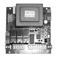
1) Unscrew the cover screws and lift the cover. Check that the electronic unit is in good order. In case of doubt do not install the unit and ask for
the intervention of qualified personnel. The container’s accessories (screws, round seal, cable glands) must not be left within the reach of
children since they are a potential danger.
2) Check that the electronic unit is properly fixed to its box. If not, tighten all screws or provide the missing screws.
3) Place the unit near the gate so that the system connection wires’ length is reduced to
the minimum.
Caution: For the unit’s correct operation the wires connected to it must not be longer than 10
metres.
4) For increased weather protection we recommend to place the unit under a roof or, even better, in an enclosure having two side walls.
Wherever possible, it is advisable
to install the unit at a minimum 1,5 mt level above the ground to keep it out of the reach of childr
en.
5)
Before proceeding to assembly place the container so that the side fitted with the cable glands is directed towards the grou
nd.
Caution: Do not assemble the container on wood surfaces.
6) Insert the supplied round seal in its seat. Make sure the two ends meet at the centre of the side to which the cable glands are fitted.
7)
Lift the mobile portion of the connector and proceed to connect the unit wires as described in the following chapters.
D) - Operation
1) Definitions of Controls
Start (dip swtch 4 = ON)
Input connected to a push-button placed outside the unit. It is employed to request the gate’s opening or closure. This input is usually connected to a
key push-button.
Pedestrian Start (dip swtch 4 = ON)
Input connected to a push-button placed outside the unit. It is employed to request the partial opening of the gate to allow the passage of persons or
animals. The gate opens for 7 seconds..
Opening Start (dip swtch 4 = off)
Input connected to a push-button placed outside the unit. It is employed to request the opening of the gate.
Closing Start (dip swtch 4 = off)
Input connected to a push-button placed outside the unit. It is employed to request the closure of the gate.
2) Definitions of Safety devices
Stop
Input connected to a push-button or switch placed outside the unit. It is employed to cause the gate’s immediate stop. This control must used in an
emergency situation.
Photo-cell
Input connected to an optical barrier. It detects and signal the passage of persons or vehicles in the area crossed by the gate or in the nearby area.
Photostop
Input connected to an optical barrier. It detects and signal the passage of persons or vehicles in the area crossed by the gate or in the nearby area.
Opening Limit Switch
Input connected to a switch placed outside the unit. The switch operates when the gate has completed its opening phase. When it is operated it
causes the gate’s immediate stop.