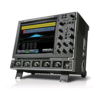
Do you have a question about the LeCroy Waverunner2 LT584 Series and is the answer not in the manual?
LeCroy warrants oscilloscope products for normal use for three years from shipment.
Help on installation, calibration, and use of equipment available from Customer Service Center.
Provides customer support services including extended warranty and budget maintenance costs.
Continual refinement and improvement of products may lead to minor manual discrepancies.
Procedures for returning products for maintenance and repair services.
Instructions for returning products, including required information and authorization.
Lists items included with the standard configuration of the oscilloscope.
Help on installation, calibration, and use of equipment available from Customer Service Center.
Details operating environment parameters like temperature, humidity, and altitude for safe operation.
Explains symbols and indications on the instrument or manual that alert users to safety aspects.
Lists the different Waverunner2 LT series models available.
Details bandwidth, input impedance, sensitivity, and resolution of the vertical system.
Covers timebases, time/div range, clock accuracy, and interpolator resolution.
Details sample rates, acquisition points, and acquisition modes.
Lists trigger modes, sources, coupling, delay, and frequency limits.
Describes color display type, resolution, screen saver, and analog persistence features.
Details remote control options (GPIB, RS-232, Ethernet) and ports.
Outlines operating conditions, CE, UL, and cUL approvals.
Describes the MPC603e processor, its circuit blocks, power supply, and peripherals.
Details the main board sections including front end, ADC, trigger, timebase, and control.
Explains input voltages, output voltages, power switch operation, and cooling.
Lists external traceable signal generators and measurement equipment needed for verification.
Procedures to measure channel and external trigger input impedance across different couplings.
Methods to test channel and external trigger leakage current by measuring voltage.
Procedures to measure RMS noise on all channels under various input and timebase settings.
Measures DC accuracy of voltage measurements against specified limits using a voltage reference source.
Verifies offset accuracy at 5mV/div with a cancelled ±1 Volt signal.
Ensures the system meets bandwidth specifications using a signal generator and power meter.
Tests trigger capabilities for standard edge triggers across different DC levels and slopes.
Checks time base accuracy using an external sine wave generator at 0.1 MHz.
Outlines critical safety warnings and antistatic procedures for servicing.
Instructions for upgrading firmware via floppy disk or memory card.
Provides diagnostic flow charts for common problems like fan, power supply, and display issues.
Details the procedure for replacing blown line fuses in the oscilloscope's power supply.
Step-by-step instructions for removing the upper cover, with or without a printer.
Procedures for removing the bottom cover assembly, including screw locations.
Instructions for removing the printer assembly, including cable and screw disconnections.
Steps to remove the floppy drive assembly, including cable and frame screw disconnection.
Detailed instructions for removing the CPU board, including cables and screws.
Steps for removing the main board, including cable disconnection and screw removal.
Procedures for removing the power supply assembly, including harnessing belt and connector disconnection.
Instructions for removing the front panel assembly, including screws, inverter plate, and LCD connections.
Steps for removing the rear panel assembly, including screws and fan motor fasteners.
Schematic diagram for Channel 1 Front End circuits.
Schematic diagram for Channel 2 Front End circuits.
Schematic diagram for Channel 3 Front End circuits.
Schematic diagram for Channel 4 Front End circuits.
Schematic for the trigger system circuits.
Schematic for DC Generation circuits.
Schematic diagram for the power connector and power board interface.
| Brand | LeCroy |
|---|---|
| Model | Waverunner2 LT584 Series |
| Category | Test Equipment |
| Language | English |


