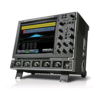
Do you have a question about the LeCroy Waverunner2 LT374M and is the answer not in the manual?
Covers product warranty terms, duration, and conditions for LeCroy oscilloscope products.
Information on obtaining help for installation, calibration, and usage of LeCroy equipment.
Details LeCroy's customer support services and extended warranty options.
Explains LeCroy's commitment to product refinement and potential documentation discrepancies.
Procedures for returning products for maintenance and repair services.
Steps and information required for returning products for service, including RAN.
Lists the standard accessories shipped with the oscilloscope.
Contact points for installation, calibration, and usage support.
Specifies operating environment parameters like temperature, humidity, and altitude.
Lists the different Waverunner2 series models and their channel configurations.
Details specifications for bandwidth, impedance, sensitivity, and resolution.
Covers timebase ranges, clock accuracy, and interpolator resolution.
Provides details on sample rates and maximum acquisition points per channel.
Describes acquisition modes like RIS, Single Shot, and Sequence Mode.
Explains Averaging, Enhanced Resolution (ERES), and Envelope functions.
Details trigger modes, sources, coupling, and delay parameters.
Features for automatic timebase, trigger, and sensitivity adjustment.
Information on probe system compatibility and scale factors.
Describes display type, resolution, screen saver, and trace options.
Covers analog and color graded persistence settings and trace display.
Details vertical and horizontal zoom capabilities, and autoscroll function.
Information on processor, processing memory, and real-time clock.
Specifies waveform and zoom/math trace storage capabilities.
Describes setup storage options including non-volatile memories and floppy drive.
Lists available interfaces like GPIB, RS-232-C, Ethernet, and ports.
Details calibrator signal and control signal outputs.
Specifies operating conditions, CE approval, and UL/cUL certifications.
Covers auto calibration, power requirements, battery backup, and warranty.
Provides physical dimensions and weight specifications.
Lists standard math functions available for signal processing.
Lists standard measurement parameters like amplitude, frequency, and delay.
Describes limit testing using masks and setting pass/fail conditions.
Mentions extended math and measurement options.
Lists additional math tools like absolute value, differentiate, and exponential functions.
Details cursor measurements for relative and absolute time/voltage.
Lists extended measurement tools such as cycle median and time difference.
Introduces WaveAnalyzer capabilities for FFT, averaging, and histograms.
Describes standard WaveAnalyzer tools like histograms and FFT power averaging.
Lists available application solutions like JTA, DFP, and PMA.
Mentions free software utilities like ScopeExplorer and MaskMaker.
Covers basic trigger types like Edge, Slope, Window, and Line.
Details SMART trigger types including State/Edge, Dropout, Pattern, and TV.
Explains SMART triggers for signal/pattern width, interval, and slew rate.
Describes hardcopy functions, supported printers, and formats.
Covers waveform saving to disk and output formats.
Lists the documentation included with the oscilloscopes, including manuals and software utilities.
Describes the MPC603e processor, its architecture, and power supply requirements.
Details the main board structure, including front end, ADC, trigger, and timebase components.
Explains the purpose of performance verification procedures and traceable calibration.
Lists quantifiable performance limits that are tested for verification.
Recommends annual calibration for the oscilloscope under normal use conditions.
Lists external test equipment needed for performance verification procedures.
Basic instructions for powering on the oscilloscope and waiting for stabilization.
Details the procedure for measuring input impedance using a high-precision digital multimeter.
Specifies steps for testing DC and AC 1MΩ input impedance on channels.
Describes the test procedure for measuring leakage current across input channels.
Specifies steps for measuring channel leakage current using a DMM.
Explains noise testing procedures with open inputs across different settings.
Defines test limits and the procedure for measuring RMS noise.
Details the procedure for measuring DC accuracy at 0V offset setting.
Describes the test procedure for offset accuracy at 5mV/div with a ±1 Volt signal.
Explains the purpose of bandwidth testing and the required external source.
Explains testing trigger capabilities for standard edge trigger cases.
Details channel trigger testing at 0 division threshold with DC coupling.
Details channel trigger testing at +3 divisions threshold with DC coupling.
Details channel trigger testing at -3 divisions threshold with DC coupling.
Details external trigger testing at 0 division threshold with DC coupling.
Details external trigger testing at +3 divisions threshold.
Details external trigger testing at -3 divisions threshold.
Details external/10 trigger testing at 0 division threshold with DC coupling.
Details external/10 trigger testing at +3 divisions threshold.
Details external/10 trigger testing at -3 divisions threshold.
Introduces smart trigger functionality for pulse width detection.
Details testing trigger on pulse widths less than and greater than 10 nsec.
Details testing trigger on pulse widths less than and greater than 100 nsec.
Explains the procedure for testing time base accuracy using a sine wave generator.
Introduces the maintenance section covering maintenance, calibration, and troubleshooting.
Details safety warnings for personal injury and instrument damage during servicing.
Outlines precautions against static electricity to protect components during handling.
Explains firmware upgrading via floppy disk or memory card interface.
Details the steps for performing firmware updates from floppy and card media.
Lists available software options like EMM, WAVA, MC01, and JTA.
Explains how to change software options by entering an option key.
Lists required test equipment and spare parts for service.
Provides a table of LT Series spare parts with part numbers and assembly details.
Details procedures for exchanging processor and main boards.
Explains how to load the serial number into a new processor board.
Describes the method for adjusting after exchanging the main board.
Outlines the procedure for confirming voltages after power board exchange.
Introduces troubleshooting information for qualified personnel and lists common symptoms.
Details how to replace line fuses, including part numbers and procedures.
Guides troubleshooting down to the board level and refers to service offices.
| Bandwidth | 500 MHz |
|---|---|
| Sample Rate | 2 GS/s |
| Channels | 4 |
| Vertical Resolution | 8 bits |
| Input Coupling | AC, DC, GND |
| Display | 10.4" Color LCD |
| Input Impedance | 1 MΩ |
| Maximum Input Voltage | 400 V |
| Trigger Modes | Edge, Pulse Width, TV, Logic, Dropout, Interval |
| Interface | GPIB, USB |


