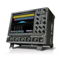
Do you have a question about the LeCroy WavePro 7300A and is the answer not in the manual?
The legal agreement governing the use of LeCroy X-Stream software, requiring user acceptance.
General information and warnings for safe instrument operation.
Guidelines for proper power and ground connections, including safety precautions.
Overview of the instrument's front panel controls, logically grouped by function.
Details on resetting WaveMaster and WavePro scopes to default settings.
Procedure for adding new software options using a key code.
Procedure for reloading the base OS and application software using a recovery routine.
Step-by-step guide for performing a system recovery, including network and hardware connections.
Instructions for activating Windows on the scope via internet or phone.
Describes LeCroy's ProLink Adapters (LPA) for connecting signals via BMA, SMA, or BNC connectors.
Explains LeCroy's ProBus probe system for automatic gain and offset correction from probes.
Step-by-step guide to selecting sampling modes like Single-shot, Sequence, or RIS.
Details on Sequence mode, its capabilities for capturing segments, and time measurements.
How to determine trigger level, slope, source, and coupling for effective triggering.
How to save or recall scope settings to or from hard disk, floppy disk, or LAN location.
Step-by-step guide to setting up a histogram for a single parameter.
Using cursors (lines, cross-hairs, arrows) as markers for fast and accurate measurements.
Steps to set up parameter math operations on selected parameters.
Adding custom parameters, functions, display algorithms, or routines to the scope interface.
Steps to create an example Visual Basic Plugin for CustomDSO.
Extends documentation capabilities by creating annotated notebook entries with waveforms, setups, and annotations.
General information on channel analysis for finding signal quality problems in head signals.
Specifying selective areas of the head signal using Analyze Region cursors or Read Gate.
Analyzing PRML head signal quality by emulating the PRML channel.
| Bandwidth | 3 GHz |
|---|---|
| Channels | 4 |
| Vertical Resolution | 8 bits |
| Display Type | TFT LCD |
| Input Coupling | AC, DC, GND |
| Timebase Accuracy | ± 5 ppm |
| Vertical Sensitivity | 1 mV/div to 1 V/div |
| Input Impedance | 50 Ω, 1 MΩ |
| Display Size | 10.4 inches |
| Maximum Input Voltage | 400 V (DC + AC peak) |
| Trigger Modes | Edge |
| Interface | USB, Ethernet, GPIB |
| Operating Temperature | 0 to 50 °C |
| Weight | 12 kg |


