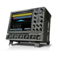
Do you have a question about the LeCroy Waverunner2 LT374 Series and is the answer not in the manual?
LeCroy warrants oscilloscope products for normal use within specifications for three years.
Assistance on installation, calibration, and use is available from the Customer Service Center.
Procedures for returning products for maintenance and repair services.
Instructions for returning a product, including obtaining a Return Authorization Number (RAN).
Provides contact information for local offices and service centers for product assistance.
Details operating environment parameters like temperature, humidity, and altitude.
Explains various safety symbols and their meanings used in the manual and on the instrument.
Describes the procedure for turning on the oscilloscope and the auto-calibration process.
Details specifications for bandwidth, input impedance, sensitivity, and resolution.
Specifies timebase ranges, clock accuracy, and interpolator resolution.
Details single shot sample rates and maximum acquisition points per channel.
Describes acquisition modes and processing features like ERES and Averaging.
Details display type, resolution, screen saver, trace count, and grid styles.
Lists remote control, GPIB, RS-232-C, Ethernet, floppy drive, and PC card slot interfaces.
Specifies operating conditions, CE, and UL/cUL approvals.
Lists standard math and measure tools available for signal processing.
Introduces procedures for verifying oscilloscope performance and characteristics.
Lists quantifiable performance limits that are tested.
Lists external traceable signal generators and measurement equipment required for tests.
Provides instructions for turning on the oscilloscope and initial checks.
Specifies procedures for testing DC 1MΩ channel input impedance.
Details procedures for testing AC 1MΩ channel input impedance.
Details procedures for testing channel leakage current.
Details test limits and procedures for RMS noise measurement.
Introduces the test for DC accuracy of voltage measurements.
Details the procedure for measuring offset accuracy.
Details the procedure for measuring bandwidth using a power meter.
Tests trigger on pulse width less than and greater than 10 nsec.
Explains testing trigger capabilities for edge trigger cases.
Details testing channel trigger at a 0 division threshold with DC coupling.
Highlights safety symbols and precautions for servicing.
Outlines the procedure for updating the instrument's firmware.
Outlines procedures for exchanging main and processor boards.
Introduces troubleshooting information for qualified personnel.
Flowchart for diagnosing and resolving fan problems.
Flowchart for diagnosing power supply voltage issues.
Step-by-step instructions for removing the upper cover assembly.
Step-by-step instructions for removing the CPU board.
Step-by-step instructions for removing the bottom cover assembly.
Step-by-step instructions for removing the power supply assembly.
Lists replaceable parts for the upper cover assembly.
Lists replaceable parts for the CPU board assembly.
Step-by-step instructions for removing the main board.
Step-by-step instructions for removing the front panel assembly.
Lists replaceable parts for the main frame and side frames.
Describes the LCD assembly and its replaceable parts.
| Channels | 4 |
|---|---|
| Vertical Resolution | 8-bit |
| Input Coupling | AC, DC, GND |
| Timebase Accuracy | ±5 ppm |
| Input Impedance | 1 MΩ, 50 Ω |
| Trigger Types | Edge |
| Interface | USB |
| Display | 10.4-inch TFT LCD |
| Input Voltage Range | 1 MΩ: ±400 Vpk, 50 Ω: ±5 Vpk |


