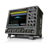
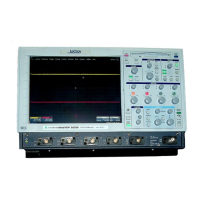
Do you have a question about the LeCroy WavePro 7200A and is the answer not in the manual?
Details the specifications for the vertical system, including bandwidth, input channels, and sensitivity.
Covers the specifications for the horizontal system, including timebases and time/div range.
Describes the acquisition system's capabilities, including sample rates and memory options.
Explains the different acquisition modes available, such as single-shot, sequence, RIS, and roll mode.
Details the triggering system's capabilities, including modes, sources, coupling, and delay settings.
Contains essential information and warnings for safe instrument operation and adherence to safety precautions.
Explains the meaning of various safety symbols found on the instrument and in the manual to alert users to important considerations.
Details the logically grouped analog and special functional control buttons and knobs on the instrument's front panel.
Describes the process of reloading the base operating system and oscilloscope application to restore a clean copy of the installed image.
Outlines the step-by-step procedure for restoring the instrument's software using the provided recovery routine.
Explains how LeCroy's ProLink Adapters enable signal connection in three different ways using BMA, SMA, and BNC connectors.
Describes LeCroy's ProBus probe system for complete measurement solutions, offering advantages over standard connections.
Describes the sequence mode for capturing and processing fixed-size segments of a waveform.
Details how to adjust the vertical sensitivity (volts/division) and position (offset) of a channel waveform.
Guides on setting up the timebase using front panel Horizontal controls and menu bar options for additional setups.
Describes the Autosetup function that automatically configures timebase, trigger, and sensitivity for displaying various signals.
Explains the different trigger modes: Auto, Normal, Single, and Stop, and their operational behavior.
Introduces various trigger types, including Edge and SMART Triggers like Width, Glitch, Interval, Qualified, State, Dropout, Logic, Serial, and Aux Input.
Details sophisticated triggers for using basic or complex conditions, including Width, Glitch, and Interval triggers.
Explains the use of cursors as markers for making fast, accurate measurements on waveform grids.
Introduces parameters as tools to automatically calculate waveform properties like rise-time and RMS voltage.
| Bandwidth | 2 GHz |
|---|---|
| Sample Rate | 10 GS/s |
| Channels | 4 |
| Vertical Resolution | 8 bits |
| Input Coupling | AC, DC, GND |
| Maximum Input Voltage | 400 V (DC + Peak AC) |
| Timebase Accuracy | ±5 ppm |
| Input Impedance | 50 Ω, 1 MΩ |
| Display | 10.4-inch color LCD |
| Trigger Types | Edge |
| Interface | USB, LAN, GPIB |
| Operating Temperature | 0°C to 50°C |


