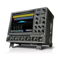
Do you have a question about the LeCroy Waverunner2 Series and is the answer not in the manual?
Details warranty terms, product assistance, and maintenance agreements.
Outlines procedures for returning and servicing the oscilloscope.
Provides contact information for LeCroy support centers.
Defines operating conditions and explains safety symbols.
Details bandwidth, impedance, sensitivity, and resolution of vertical input.
Covers timebase ranges, sample rates, and acquisition modes.
Describes trigger modes, coupling, delays, and frequency capabilities.
Details color display, resolution, and persistence settings.
Lists operating conditions and CE/UL/cUL safety certifications.
Explains available math functions and measurement tools.
Details basic, SMART, and exclusion triggers, plus hardcopy capabilities.
Describes the MPC603e processor, circuit blocks, and power supply.
Details Front End, A/D Converter, Trigger, and Timebase sections.
Explains the power supply unit's components, switch, and cooling.
Lists required equipment and procedures for recording results.
Details how to measure input impedance for different couplings and channels.
Outlines procedures for testing leakage current and RMS noise levels.
Details methods for verifying DC accuracy and offset voltage measurements.
Explains tests for bandwidth, trigger level accuracy, and time base performance.
Highlights critical safety measures for servicing and handling components.
Provides steps for upgrading software and firmware via floppy or card.
Details the process for replacing CPU, Main, and Power boards.
Offers guidance for diagnosing issues like fan, display, or printer problems.
Instructions for safely replacing blown line fuses in the oscilloscope.
Guides for removing upper, bottom, and rear panel assemblies.
Details procedures for replacing printer, floppy, CPU, main, and power boards.
Steps for removing the front panel, LCD, and associated components.
| Channels | 2 or 4 |
|---|---|
| Input Coupling | AC, DC, GND |
| Display Size | 10.4" |
| Display Type | Color LCD |
| Vertical Resolution | 8 bits |
| Input Impedance | 1 MΩ or 50 Ω |
| Trigger Types | Edge, Glitch, Width, Window, Interval, Dropout, Runt, Slew Rate, TV, Pattern, State, Serial |
| Connectivity | USB, LAN, GPIB (optional) |
| Operating System | Windows |
| Display | 10.4 inch XGA TFT LCD |
| Maximum Input Voltage | 400 V (DC + peak AC) |

