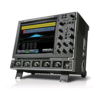
Do you have a question about the LeCroy WAVERUNNER 6000 SERIES and is the answer not in the manual?
Details LeCroy's warranty terms for oscilloscope products, including limitations and coverage.
Provides information on how to obtain help with installation, calibration, and usage of LeCroy equipment.
Explains how LeCroy refines products and how manual details might differ from current versions.
Information on obtaining help from LeCroy Customer Care Center, European, and Japan service centers.
Covers operating environment parameters like temperature, humidity, and altitude for safe use.
Details the oscilloscope's power source requirements, fuse specifications, and grounding.
Specifies vertical system characteristics including bandwidth, sensitivity, resolution, and offset.
Details horizontal system parameters such as timebases, clock accuracy, and deskew range.
Describes the acquisition system's sample rates, memory options, and trigger capabilities.
Outlines available trigger modes, sources, coupling, and delay settings for signal capture.
Lists available interfaces for remote control and data transfer, including USB, GPIB, and Ethernet.
Specifies operating and non-operating environmental conditions for the oscilloscope.
Provides a high-level overview of the WaveRunner 6000 system components and their interconnections.
Details the computer system, including processor, operating system, memory, and storage devices.
Describes the PCI card's role as an interface between the PCI bus and the acquisition system.
Explains the color LCD module, inverter, and touch screen functionalities.
Provides a block diagram and detailed description of the acquisition system components.
Introduces procedures for verifying the WaveRunner 6000 Series oscilloscope's performance and specifications.
Lists the essential external traceable signal generators and digital multimeter needed for performance checks.
Details procedures and specifications for measuring channel and external trigger input impedance.
Outlines the procedure and specifications for testing channel and external trigger leakage currents.
Defines DC accuracy specifications and procedures for positive and negative measurements across different ranges.
Specifies offset accuracy and details procedures for positive and negative offset measurements.
Ensures system bandwidth meets specifications for different models using controlled external sources.
Tests trigger capabilities for standard edge triggers across different DC levels and slopes.
Details the procedure for verifying the accuracy of the 10 GHz clock and time base.
Provides information on disassembling, assembling, maintaining, calibrating, and troubleshooting the WaveRunner 6000.
Highlights crucial safety warnings, including those related to personal injury and equipment damage.
Details step-by-step procedures for disassembling and reassembling the instrument's components.
Guides users through installing new X-Stream DSO application software and device drivers.
Outlines procedures for replacing major boards like the processor and hard drive.
Lists recommended test equipment and spare parts for servicing the WaveRunner.
Explains how to access the service menu for diagnostics and testing.
Provides troubleshooting information, common symptoms, likely causes, and resolution steps.
Lists field-replaceable units specific to the WaveRunner 6030, 6050, 6051, 6100, and 6200 models.
Lists field-replaceable units specific to the WaveRunner 6030A, 6050A, 6051A, 6100A, and 6200A models.
Illustrates the procedure for removing the WaveRunner's top cover, showing components and screws.
Depicts the bezel removal and acquisition board installation process, including specific items.
Shows the top-side assembly of the acquisition board, detailing heatsinks and related components.
Details the assembly of the processor tray, including motherboard, CPU cooler, and memory modules.
| Brand | LeCroy |
|---|---|
| Model | WAVERUNNER 6000 SERIES |
| Category | Test Equipment |
| Language | English |


