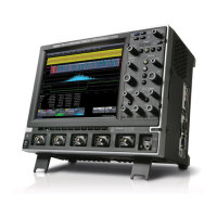
Do you have a question about the LeCroy Waverunner2 LT264 Series and is the answer not in the manual?
Details on bandwidth, impedance, resolution, sensitivity, and isolation.
Parameters for timebases, time/div range, clock accuracy, and interpolator.
Sample rates, acquisition points, and acquisition modes for the instrument.
Details on averaging, enhanced resolution, and envelope processing.
Modes, sources, coupling, delay, and frequency limits for triggering.
Details on the display type, resolution, screen saver, and trace management.
Information on processor, processing memory, and realtime clock.
Details on remote control, GPIB, RS-232C, Ethernet, floppy drive, and ports.
Standard automated measurements for parameters like amplitude, frequency, and delay.
Features for FFT, averaging, histograms, and advanced waveform analysis.
Standard trigger modes including edge, slope, window, and line triggers.
Advanced trigger types like state/edge qualified, dropout, pattern, and TV triggers.
Triggers based on signal/pattern width, interval, slew rate, and runts.
Details on the MPC603e processor, circuit blocks, and power supply.
Information on SDRAM configuration, normal, burst, and refresh access timing.
Overview of the main board sections: Front End, A/D Converter, Trigger, Timebase.
Detailed functions of the front end, including protection, attenuation, and HFE428.
Description of time base circuits: MCG426, MTB411A, and MST429A.
Procedures for verifying oscilloscope performance and characteristics.
Quantifiable performance limits tested for the oscilloscope.
List of external traceable signal generators and measurement equipment needed.
Procedures for measuring channel and external trigger input impedance.
Detailed steps for testing DC 1MΩ, AC 1MΩ, and DC 50Ω input impedance.
Procedures for measuring leakage current on channel and external trigger inputs.
Method for testing RMS noise on all channels with open inputs.
Procedure for measuring DC accuracy of voltage measurements at 0V offset.
Procedure for testing offset accuracy at 5mV/div with a ±1 Volt signal.
Procedures to ensure the system meets bandwidth specifications.
Tests for trigger capabilities across different DC levels and slopes.
Procedures for testing trigger behavior based on pulse width.
Procedure to check time base clock accuracy using an external sine wave generator.
General safety warnings for qualified personnel performing servicing.
Guidance for diagnosing and resolving common instrument problems.
| Channels | 4 |
|---|---|
| Vertical Resolution | 8 bits |
| Input Coupling | AC, DC, GND |
| Max Input Voltage | 400 V (DC + peak AC) |
| Trigger Modes | Edge, Pulse Width |
| Display | Color LCD |
| Display Size | 10.4 inches |
| Display Type | Color LCD |
| Input Impedance | 1 MΩ |


