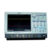
Do you have a question about the LeCroy WaveSurfer 400 Series and is the answer not in the manual?
Details warranty, product support, and assistance.
Covers installation, operation, and safety guidelines.
Outlines technical specifications for the oscilloscope models.
Provides a high-level block diagram of the oscilloscope system.
Details the components and functions of the main circuit board.
Explains the analog signal processing front-end circuitry.
Describes the ADC system based on HAM631.
Details the trigger system components (HTR420, MST429A).
Explains the time base circuits (MCG426, MTB411A, TDC, MST429A).
Describes the functions of the calibrator circuit.
Outlines functions of the SCAN DAC.
Details functions of the main board control system.
Describes the oscilloscope's processor, OS, memory, and interfaces.
Explains the PCI card's interface and functions.
Details the local buses for acquisition data and control.
Describes the Dallas OneWire interface for scope ID.
Explains the audio amplifier for the internal speaker.
Describes the front panel assemblies (panel board, keyboard).
Details the front panel keyboard assembly components.
Explains the panel board functions (encoders, touchscreen).
Covers the LCD module, backlight inverter, and touchscreen.
Details the oscilloscope's power supply unit.
Specifies the supported AC input voltage ranges.
Lists the various output voltages provided by the power supply.
Explains the basic operation of the power supply converters.
Describes the DC/DC converters for +5VANA and 2.5V.
Details DC/DC converters for +9V and +12V.
Explains the forward converter for -5V and -12V.
Describes filter circuits for analog outputs.
Lists power supply connector assignments.
Explains how to adjust output voltage ranges.
Details the +5VSB standby supply rail.
Lists the required control signals for the power supply.
Describes the over-current protection mechanisms.
Explains the over-temperature protection features.
Details the over-voltage protection features.
Introduces procedures for verifying oscilloscope performance.
Lists quantifiable performance limits to be tested.
Specifies the recommended calibration cycle.
Lists necessary external test equipment for verification.
Details input impedance characteristics.
Details procedures for measuring channel input impedance.
Outlines procedures for measuring external trigger input impedance.
Details leakage current specifications.
Details procedures for measuring channel leakage current.
Outlines procedures for measuring external trigger leakage current.
Details specifications and procedures for peak-peak noise.
Details DC accuracy specifications.
Details the procedure for measuring positive DC accuracy.
Details the procedure for measuring negative DC accuracy.
Details offset accuracy specifications.
Details the procedure for measuring positive offset accuracy.
Details the procedure for measuring negative offset accuracy.
Details bandwidth specifications.
Explains the purpose and method for testing bandwidth.
Details trigger level specifications.
Describes tested trigger capabilities.
Details trigger level testing at 0 division threshold.
Details trigger level testing at +2.5 division threshold.
Details trigger level testing at -2.5 division threshold.
Details time base accuracy specifications.
Explains the time base accuracy test setup.
Details the procedure for verifying clock accuracy.
Outlines information for disassembly, assembly, and maintenance.
Details safety measures to avoid injury and instrument damage.
Advises on precautions against static electricity for component handling.
Describes steps for updating the oscilloscope's software.
Presents the EULA for the X-Stream software.
Guides on installing necessary device drivers.
Provides steps to restore the oscilloscope's operating system.
Covers procedures for replacing circuit boards.
Explains how to copy files for network sharing.
Details how to create a startup disk for network operations.
Guides on updating the hard disk via network.
Outlines steps for initial setup after hard disk update.
Describes how to validate the installed software.
Guides on initializing the panel setup.
Details the necessary BIOS settings for system operation.
Provides steps for exchanging the system battery.
Guides on updating the system BIOS.
Lists recommended test equipment and spare parts.
Details how to access and use the service menu.
Explains how to access the service menu.
Describes mainframe tests to perform.
Details calibration procedures for the system.
Details the procedure for calibrating the system's power supply.
Guides on calibrating the touch screen interface.
Covers front/ACQ system adjustments.
Details front-end adjustments like channel offset and gain.
Explains attenuator phase adjustment procedures.
Details input capacitance adjustment steps.
Covers EXT10 phase adjustment.
Outlines adjustments for high-speed waveform characteristics.
Details TDC adjustment procedures.
Explains trigger delay adjustment steps.
Details trigger hysteresis adjustment.
Explains event trigger delay adjustment.
Details odd path adjustment for signal integrity.
Guides on adjusting trigger analog time.
Explains how to adjust time difference between channels.
Details how to adjust speaker volume.
Provides troubleshooting information and flow charts.
Introduces troubleshooting information for qualified personnel.
Defines repair levels and board exchange policies.
Provides a flowchart for initial troubleshooting steps.
Offers troubleshooting steps for power supply issues.
Provides troubleshooting for display issues.
Details troubleshooting steps for internal display malfunctions.
Outlines the oscilloscope's boot-up sequence and troubleshooting.
Guides troubleshooting for unresponsive front panel controls or touch screen.
Offers troubleshooting steps for timebase issues.
Guides troubleshooting for remote control communication issues.
Provides troubleshooting steps for vertical accuracy issues.
Offers troubleshooting steps for bandwidth related problems.
Guides troubleshooting for line trigger issues.
Lists all replaceable parts with part numbers and descriptions.
Shows a block diagram of the oscilloscope's main components.
Provides flowcharts for disassembling the instrument.
Lists replaceable parts located on the outer casing.
Lists replaceable parts on the rear and side panels.
Details the components and parts of the front panel assembly.
Guides on how to remove the front panel assembly.
Details removal of individual parts from the front panel assembly.
Lists parts related to the front panel assembly.
Lists replaceable parts for the main frame assemblies.
Guides on removing and replacing the Hard Disk Drive (HDD).
Details removing and replacing the PCI Board.
Provides steps for removing the power supply assembly.
Guides on removing the main board.
Details the procedure for removing the CPU board.
Explains how to remove the PFC circuit.
| Channels | 2 or 4 |
|---|---|
| Input Coupling | AC, DC, GND |
| Input Impedance | 1 MΩ |
| Trigger Types | Edge, Pulse Width, State, Interval, Dropout, Runt |
| Display Type | Color LCD |
| Vertical Resolution | 8-bit |
| Interface | USB |
| Display | 10.4" touchscreen |


