7-12
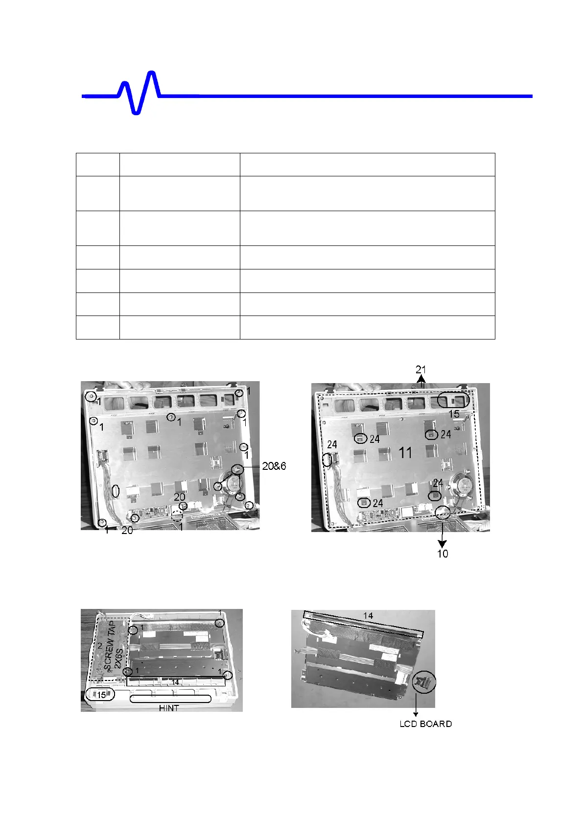
E. Removal of the Front Panel Assembly Parts
Fig. No Removal Parts Screws
E1 SPEAKER Remove the three
KB(+)3X6S(NIP)
screws on the front
chassis.
E1 INVERTER Remove the two
KB(+)3X6S(NIP)
screws on the front
chassis.
E1 BEZEL PLATE
Remove the two TT2(+)3X8S screws on the front bezel.
E1 FRONT CHASSIS
Remove the seven TT2(+)3X8S screws on the front bezel.
E2 LCD Assembly Remove the four
TT2(+)3X8S
screws on the front bezel.
E3 KEY BOARD Assembly Remove the eleven 2X6S(P) screws on the front bezel.
[E1]
NOTE: When you assemble the Front Panel Assembly, the noise shield (21) is inserted in
the groove at the edges of the front panel assy.
[E2]
Mechanical Parts & Removal
HINT: It is easy to remove the front panel parts

 Loading...


