4.4.2 Local bus for acquisition
The acquisition interface consists of 2 local buses to read out acquisition data and to
control the main board.
4.4.2.1 Control
All resource on main board is controlled through 8bit local bus.
4.4.2.2 Acquisition Data
32bit local bus is used to access the acquisition memories. Each 8bit is
connected to each channel's memories directly. (bit0-7 is connected to
ch1, bit8-15 is connected to ch2, bit16-23 is connected to ch3 and bit24-
31 is connected to ch4)
4.4.3 Dallas OneWire Interface
The Dallas onewire interface is controlled by FPGA. The 4kbits EEPROM is
connected to this interface. This device has unique id to generate scope id.
4.4.4 Audio amplifire
The audio amplifier to drive internal speaker is on PCI board. This is independent
from other PCI function.
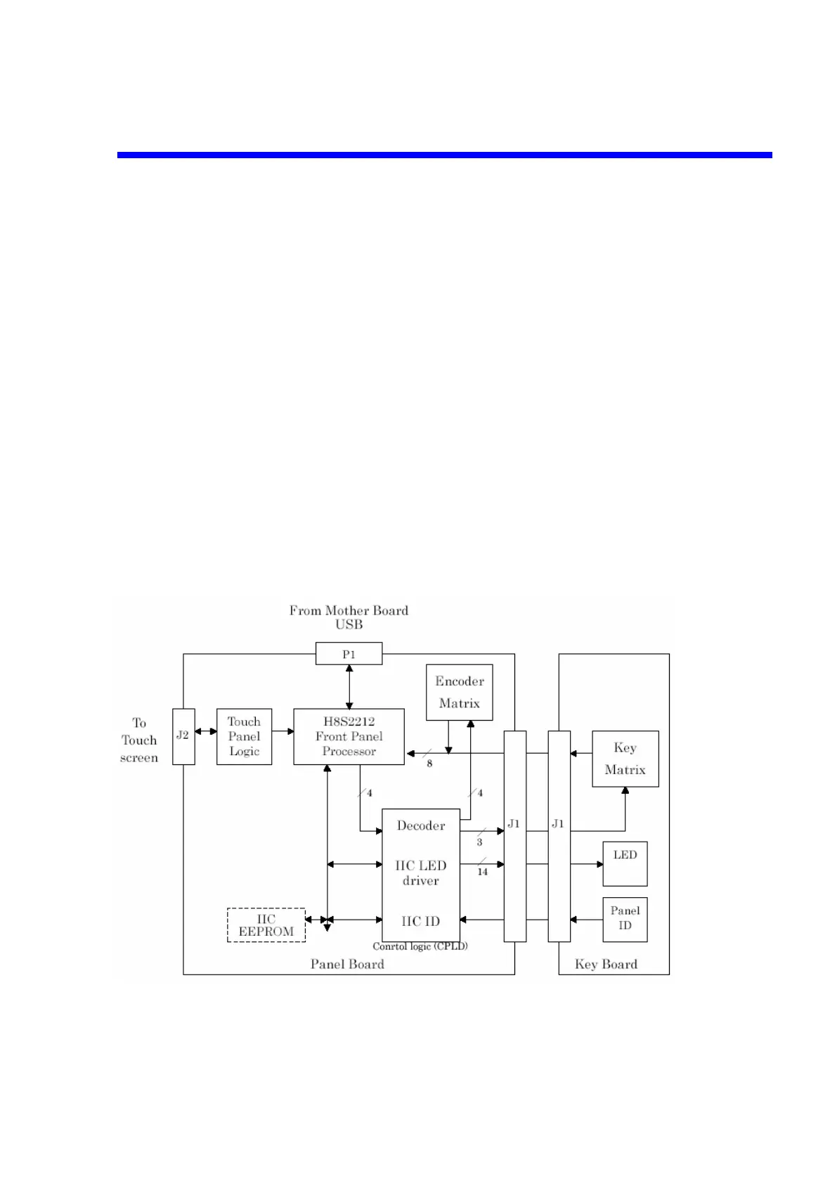
4.5 Front Panel
The front panel consists of two assemblies, the panel board and the key board
assembly.
Figure 4-11 Front Panel Block Diagram
Theory of Operation 4-13

 Loading...


