6.9.3.2.3 Attenuator phase adjustment
Adjustment standard Overshoot: 0.5% or less
Rounding: 0.5% or less
Setting CHx ⇒ DC 1MΩ, 50mV/div, 500mV/div
Adjustment method Input a 15kHz square-wave signal and adjust the attenuator phase.
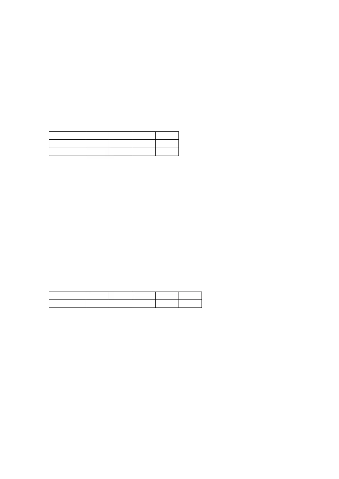
Adjustment locations
CH1 CH2 CH3 CH4
50mV/div 2C44 3C44 4C44 5C44
500mV/div 2C45 3C45 4C45 5C45
After adjusting the input capacitance, again verify the 50 mV/div attenuator phase and readjust if
necessary.
6.9.3.2.4 Input capacitance adjustment
Adjustment standard 16pF ± 1.5pF at 50mV/div
Difference between 20mV/div and 50mV/div: ±0.5pF or less
Difference between EXT and EXT10: ±0.5pF or less
Adjustment method CH1 to CH4(2) Verify the input capacitance at 50 mV/div.
Change to 20mV/div and adjust so that the difference with
the 50mV/div scale is within the standard range.
EXT Set “Edge Trigger” and verify the input capacitance at “Trigger on –
Ext” and “Impedance – DC1MΩ.”
Change to “Trigger on – Ext/10” and adjust so that the difference
with “Trigger on – Ext” is within the standard range.
Adjustment locations
CH1 CH2 CH3 CH4 EXT
Input C adj. 2C22 3C22 4C22 5C22 6C22
6.9.3.2.5 EXT10 phase adjustment
Adjustment standard Difference between 1 kHz and 1 MHz trigger points: ±0.1 div or less
Setting CH1 ⇒ 1V/div, DC 1MΩ, offset 0V
Trigger ⇒ Trigger on: Ext/10, Imp: 1MΩ, Coupling: DC, Slope: Positive, Level: 3V
Adjustment method Using a T-branch, input an approximate 10Vp-p, 1KHz sine wave signal to
CH1 and EXT.
Verify that the location of the trigger point is +3div ± 0.3div.
Next, change the frequency to 1MHz and adjust 6C6 such that the shift in
the trigger point is minimized for 1KHz.
Maintenance 6-39

 Loading...


