X-Stream Operator’s Manual
WM-OM-E Rev I 421
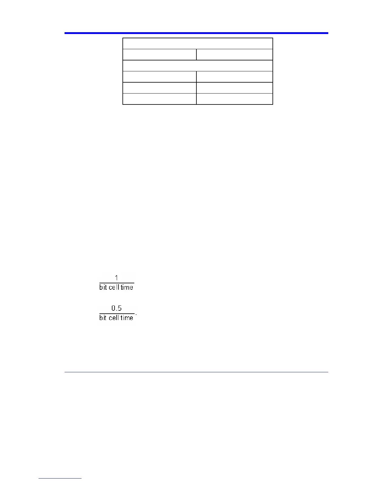
Density of Samples per pw50
Peak Detect 1
PRML
PR4 1.65
EPR4 2
E2PR4 2.31
However, the higher order PRML schemes need very complex circuits and decoders. While the
Class IV partial response (PR4) system works with three vertical levels of samples, extended
partial response 4 (E2PR4) has seven levels, and requires not only a higher resolution of ADC, but
a complicated timing and gain recovery circuit and sophisticated ML detector as well. Another
disadvantage of the more complex PRML schemes is that they are more sensitive to noise.
Principle of Equalization
The process of taking the more-or-less Lorentzian shaped head response to a magnetic transition
and turning it into a correctly shaped pulse is called equalization. This is of great importance, due to
the need of the Viterbi detector inside the PRML channel chip for correctly shaped pulses.
Essentially, equalization is performed in the read channel chip by a continuous time analog filter
(CTAF).
Noise must be eliminated before sampling occurs, or else it becomes impossible to separate it from
the head signal. Since the head signal is typically noisy, and contains pulses that are not quite the
desired shape, the DDA provides an equalization filter to reduce much of the noise and reshape the
pulses before it processes the waveform. This filter is a digital implementation of a seven-pole,
two-zero equiripple filter.
When you are using the filter, there are a number of parameters to be set. If the head signal has
already been acquired, the filter parameters can be set automatically by pressing the Train Filter
button. When this button is pressed:
• If the signal type is Peak Detect, the boost is set to zero and the -3 dB frequency is set
to:
• If the signal type is PRML (PR4, EPR4 or E2PR4) the -3 dB frequency is set to:
The best boost and -3 dB frequency are found by optimizing boost at the default -3 dB frequency,
then optimizing -3 dB at the better boost. Then optimize boost at the new -3 dB frequency, and
optimize -3 dB frequency again at the new boost. And then, if -3 dB frequency has changed by
more than a small amount, optimize the boost one final time. The goal for optimization is to
maximize the mean of the 100 worst SAM values. A typical run will recompute the filter, apply it, and