Control
Relay control
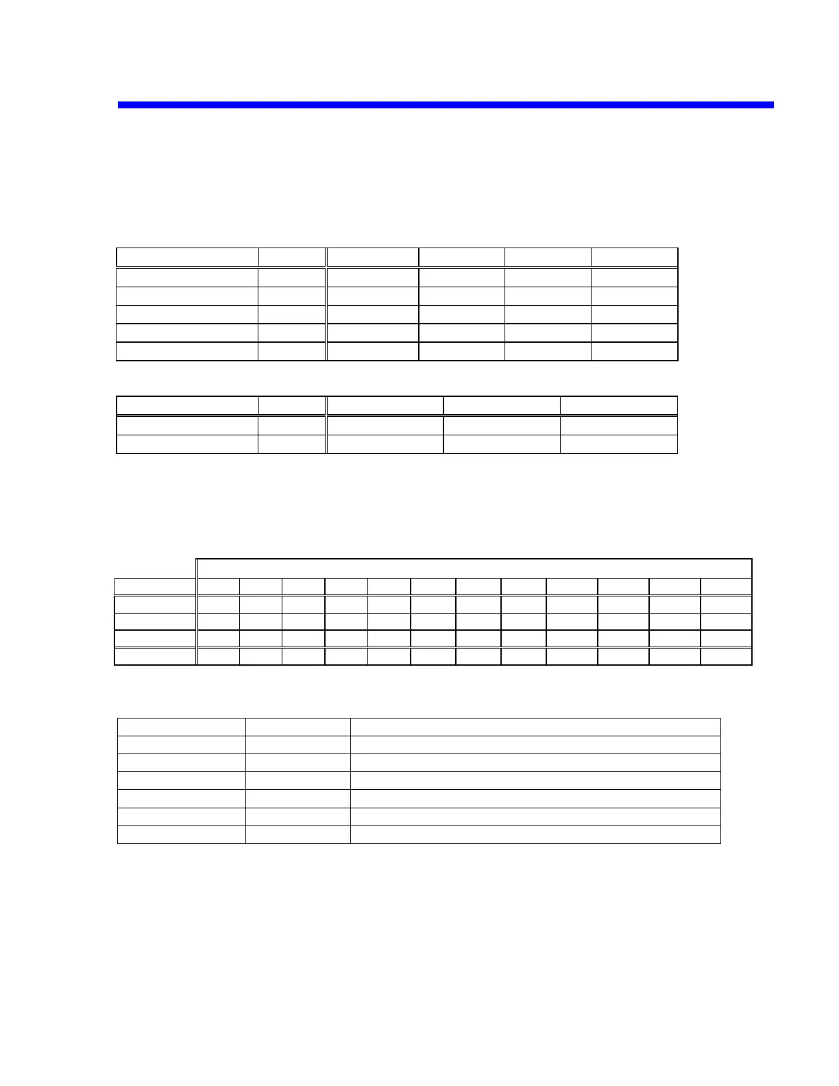
The relay of the attenuator is set by selecting the input coupling and the gain as shown in
the table below.
RL1, 2 and 5 are driven with +5V/0V, and RL3, 4 is driven with +5V/-5V.
Input coupling
Control port Relay GND 1M,DC 1M,AC 50,DC
GND/*MES RL2 H L L L
1M/*50 RL1 H H H L
AC/*DC RL5 H L H L
1/*10 RL3 H X X X
1/*100 RL4 L X X X
Switch of attenuator
Control port Relay 2mV-99mV 100mV-0.99V 1V-10V
1/*10 RL3 H L L
1/*100 RL4 H H L
Divide gain
The gain ratio in each block and input range is a table below.
At the BNC the dynamic range is 16 mV to 80V FS (full scale) and the output is 500 mV
differential (HAD631 input).
Range V/div
Block
2mV 5mV 10mV 20mV 50mV 100mV 200mV 500mV 1V 2V 5V 10V
ATT 1/*10
1 1 1 1 1 0.1 0.1 0.1 0.1 0.1 0.1 0.1
ATT 1/*100
1 1 1 1 1 1 1 1 0.1 0.1 0.1 0.1
HFE428
31.25 12.5 6.25 3.125 1.25 6.25 3.125 1.25 6.25 3.125 1.25 0.625
Total(ratio)
31.25 12.5 6.25 3.125 1.25 0.625 0.3125 0.125 0.0625 0.03125 0.0125 0.00625
Analog control voltage
Circuit name signal level Signal name
CHx OFFSET +/-4V Offset control signal
CHx GAIN 0 to +4V HFE428 gain control signal
CHx TRIG LVL1 +/-4V Trigger level control signal
CHx TRIG LVL2 +/-4V Trigger level control signal for smart trigger/window
CHx HYST 0 to +4V Trigger hysteresis control signal
INT CAL 0 to +600mV Signal each CH commonness for calibration
Theory of Operation 4-11

 Loading...
