4.2.8 Time Base
Introduction
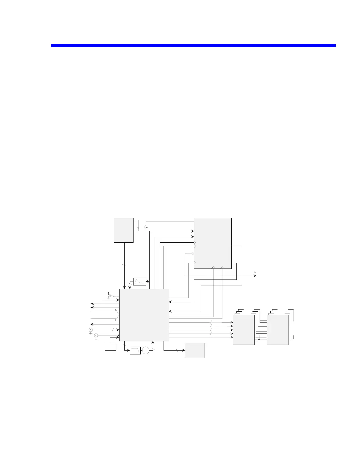
The time base includes three circuits:
• MCG426: generates sampling clocks: 12.5 MHz up to 2GHz
generates clocks for the MTB411
interleaves sampling clocks to increase sampling rate and memory
depth.
• MTB411A: Time Base System
TDC interpolator and Real Time computation
Trigger circuitry
Frequency divider
• MST429A: Single source trigger, Standard trigger, Hold off, Pulse width & interval
Multiple source trigger, State qualified, Edge qualified
Block Diagram
MTB 411
MST 429
MCG 426
HSH & ADC
SHCK_A
SHCK_B
SHCK_C
SHCK_D
2
2
2
2
MCK
TRIG
TRIG
2
Peak
Detect
MPD
10 MHz
Reference
INTREF
PHDET
VCO
VCO2G PDCK
2
2
2
RAMPST
R
A
M
PS
TRTTRT
to trigger selection
SHCK_A
SHCK_B
SHCK_C
SHCK_D
Q
Q
D
ENABLE TRIGEN
ITBUSY
MACQ
FDEND
FDCK
TR
IG
D
IT
C
TRIGD
ITCK
FDCK FDEND
MACQ
INT
2
TBCK
TSCK
TSCK TBCK
BCK
ITMB
to uP
MEMORY
MCK
DIN[7..0]
EXTREF
EXTCK
EXTREF
EXTCK
2
RT
C
RTCK
S2EDGE
Vcc
MCLR CLR
EN10MHZ
10MHZclock 10MHz
500MHZclock 500MHz
CONTROL
from uP
DIO(7:0) +
A(1:0) +
control
enable
clock 10MHz
Time Base Block Diagram
Theory of Operation 4-17
 Loading...

