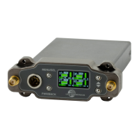
DSR4
LECTROSONICS, INC.
6
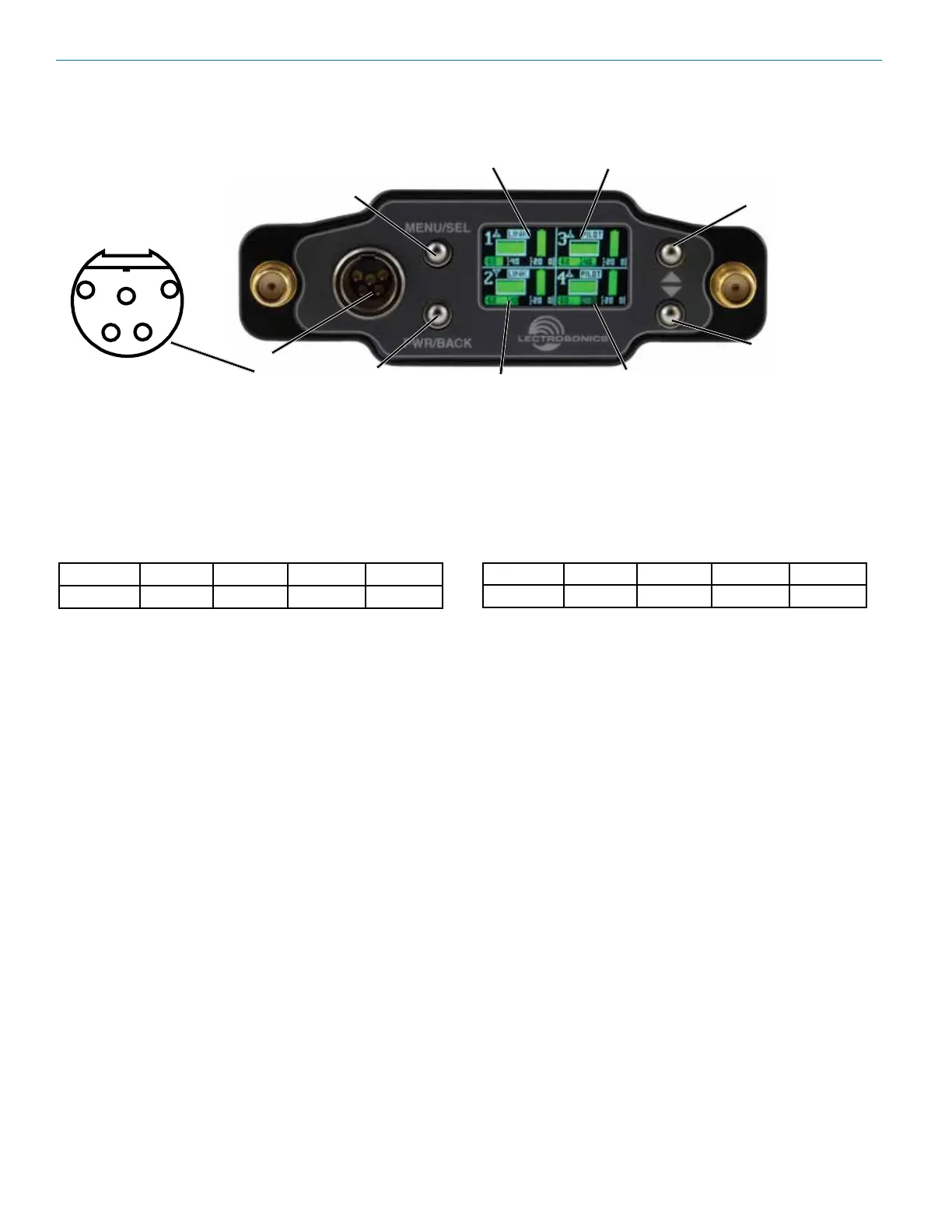
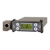
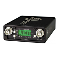
Color LCD Display
The display has one primary “home” window. PWR/
BACK goes to receiver detail screens. UP/DOWN arrows
select channel.
After Power is turned o and back on again, the unit
defaults to the Main window and to the most recent
frequencies, audio levels, transmitter battery conditions,
and other user settings. These settings are retained even
if the batteries are removed. The display illumination can
be set to time out in 5 seconds, 30 seconds, or never.
Power O
When the Front Panel Power/Back button is pressed
for several seconds, the audio output is instantly muted
(squelched) and the message “POWERING OFF...” is
displayed briey before the receiver switches o.
MENU/SEL Button
The MENU button accesses the available menus and
selects the desired setting.
PWR/BACK Button
The PWR/BACK button is used to turn the receiver on
and o. When browsing menus and making changes to
settings, press PWR/BACK to return to previous menu.
Up/Down Arrow Buttons
The UP/DOWN buttons are used to scroll or input the
various options within each menu selection.
Antenna Port (2)
TA5M Connector
Routes analog audio Channels 3 and 4 or AES3 audio
channels 1-4 to the top of the unit.
IR (infrared) Port
(just under the front panel)
Settings can be transferred between transmitter and
receiver or receiver and receiver.
USB Port
(just under the front panel)
The microB USB port can be used to connect the DSR4
to the Lectrosonics Wireless Designer software and to
perform rmware updates.
DSR4 Front Panel Controls and Functions
Audio Outputs
Audio outputs and the power inlet are located on the rear panel, accessed by a variety of dierent bottom-plate adapt-
ers. Depending on the slot receptacle or camera, either analog or digital outputs may be used by changing settings
in the receiver menu. In slots where two analog channels are accepted, audio channels 1 & 2 can be sent from the
receiver through the slot connector. In such cases, use the top connector to access audio channels 3 & 4. In slots that
accept 4 channels of audio via two balanced AES pairs, set the receiver outputs to AES3. Keep in mind that the top
panel TA5 connector will always be a duplicate of what is sent to outputs “3&4” in the audio output menu.
The front panel 5-pin connector (TA5 type) provides two balanced pairs with the following analog and AES3 pinouts:
Pin 1 Pin 2 Pin 3 Pin 4 Pin 5
Ground Audio 3 + Audio 3 - Audio 4 + Audio 4 –
DOWN Button
MENU/SELECT
Button
POWER/BACK
Button
UP Button
Receiver CH 1 Receiver CH 3
TA5
Input
Receiver CH 2
Receiver CH 4
1
2
3
4
5
Pin 1 Pin 2 Pin 3 Pin 4 Pin 5
Ground AES 1/2+ AES 1/2- AES 3/4+ AES 3/4-