Four Channel Digital Receiver
Rio Rancho, NM
7
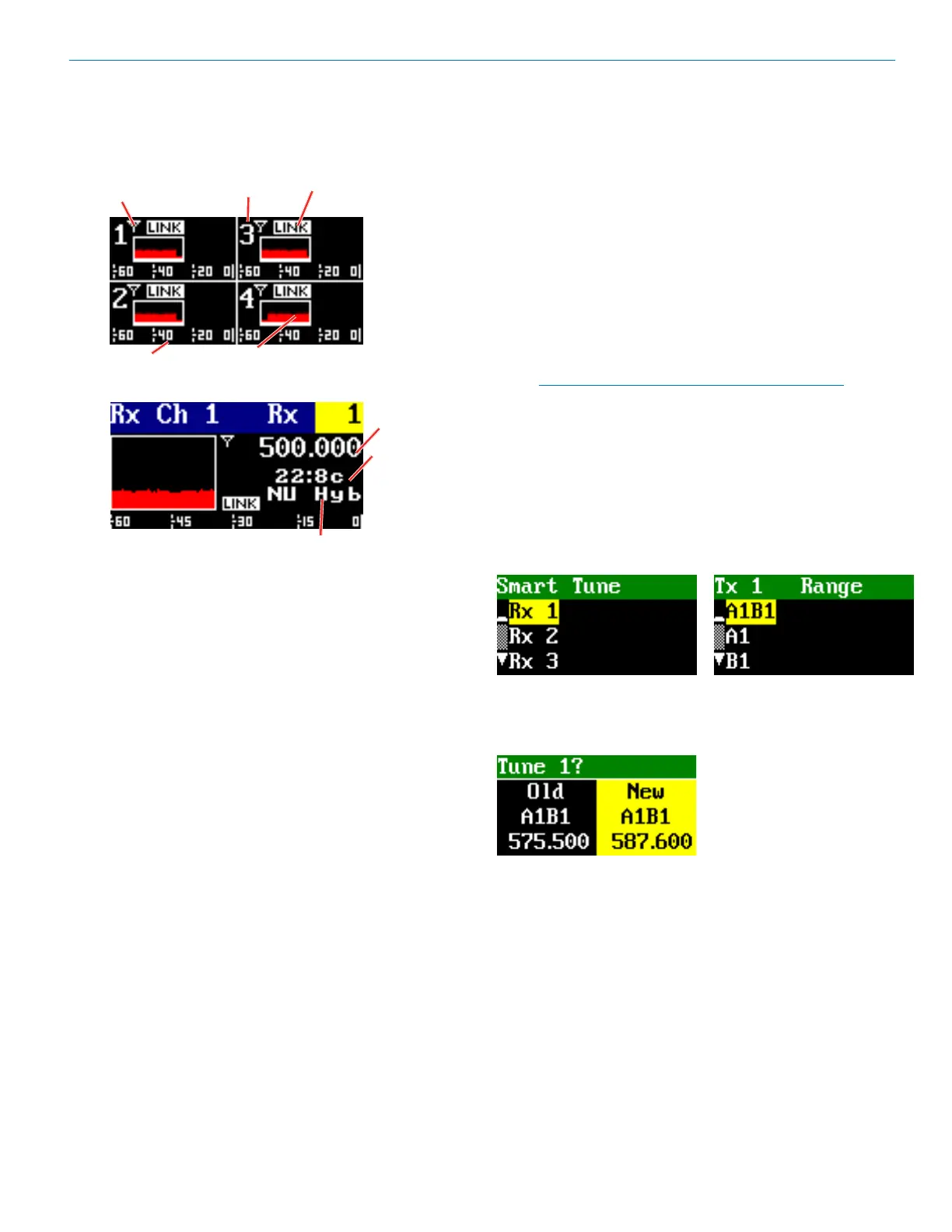
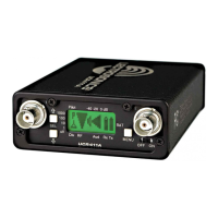
Main Window Display
The Main Window displays information concerning the
RF levels at each antenna per channel, audio modula-
tion levels, the condition of the Pilot Tone (Hybrid) or Link
(digital), and power conditions for both the receiver and
the associated transmitters. It is also the access portal to
menu selections for setting up the receiver and search-
ing for clear frequency channels.(See Menu Selections
from Main window and Frequency Scan Mode). The
PWR/BACK button will cycle between the Home screen,
showing all four channels and the channel detail screens.
Use the UP and DOWN arrows to go between individual
channels in the Channel Detail view.
• Receiver Power icon changes to a plug icon
when external power is supplied.
• Antenna Icons: Status of the vector diversity
system.
• RF Signal Strength Strip Charts: RF signal
strength indicators.
• Channel Status Indicator: Pilot tone, link and
encryption system status.
Navigating the Menus
From the Main Window, press MENU/SEL to enter the
menu, then navigate with the UP and DOWN arrows to
highlight the desired setup item. Press MENU/SEL to
enter the setup screen for that item. Refer to the Menu
Map on pages 8-9.
Menu Item Descriptions
RF Setup
Smart Tune
Smart Tune is the easiest and fastest way to scan the
local RF spectrum and nd clear operating frequencies.
The receiver will scan through the selected tuning band-
width and automatically nd “empty” areas within the
tuning range that have little or no RF energy. The receiver
will then be set to a frequency within an empty area and
prompt you to continue or use the IR function to sync to
a transmitter.
Note: Pressing BACK during an active scan will
restore the operating frequency to what it was
set at pre-scan.
Transmit frequency range is compatibility mode depen-
dent (see Compat Mode for further details). Rx 1-4 is
the rst screen you will see when you enter SmartTune.
After selecting Rx1-4, using the UP/DOWN buttons,
press MENU/SEL to open the TX Range page, then use
the UP/DOWN buttons to select the frequency range of
the transmitter.
After choosing the band, the unit will scan the available
frequency and choose the frequency with the lowest
interference and will display it as shown (the previous
frequency used and the new frequency identied).
Use the UP/DOWN arrows to toggle between them, then
MENU/SEL to choose.
Face the transmitter’s IR port within a few inches of the
receiver’s IR port and press the DOWN button to begin
the sync. In digital compat modes, if the sync is success-
ful, the message “IR Sync OK” will appear on screen. If
unsuccessful, the message will show “IR Sync Failed”.
For Hybrid compat modes, “Sync!” at the lower right will
blink, but the sync status will only show on the transmit-
ter’s display.
Channel
Audio Level
RF Signal
Strip Chart
Antenna
Status
Compat
Mode
Block/
Hex Code
Channel
Channel
Status
Indicator
Frequency