12
Installation
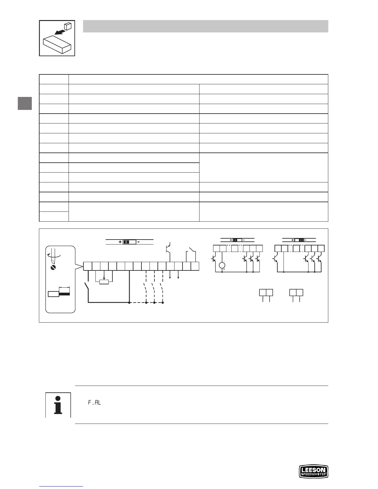
3.2.3 Control terminals
Terminal Data for control connections
1
Digital Input: Start/Stop
input resistance = 4.3kΩ
2
Analog Common
5
Analog Input: 0...10 VDC
input resistance: >50 kΩ
6
Internal DC supply for speed pot +10 VDC, max. 10 mA
25
Analog Input: 4...20 mA
input resistance: 250Ω
4
Digital Reference/Common +15 VDC / 0 VDC, depending on assertion level
11
Internal DC supply for external devices +12 VDC, max. 50 mA
13A
Digital Input: Configurable with P121
input resistance = 4.3kΩ
13B
Digital Input: Configurable with P122
13C
Digital Input: Configurable with P123
14
Digital Output: Configurable with P142
DC 24 V / 50 mA; NPN
30
Analog Output: Configurable with P150…P155
0…10 VDC, max. 20 mA
16
Relay output: Configurable with P140
AC 250 V / 3 A
DC 24 V / 2 A … 240 V / 0.22 A, non-inductive
17
V0109
Assertion level of digital inputs
The digital inputs can be configured for active-high or active-low by setting the Assertion Level
Switch (ALsw) and P120. If wiring to the drive inputs with dry contacts or with PNP solid state
switches, set the switch and P120 to “High” (+). If using NPN devices for inputs, set both to “Low”
(-). Active-high (+) is the default setting.
HIGH = +12 … +30 V
LOW = 0 … +3 V
Note
An F.AL fault will occur if the Assertion Level switch (ALsw) position does not match the
parameter P120 setting and P100 or any of the digital inputs (P121...P123) is set to a
value other than 0.