30
Commissioning
Code
Display Range
(READ ONLY)
IMPORTANT
No. Name
P525
Analog Output 0 {VDC} 10.0 See P150…P155
P527
Actual Output
Frequency
0 {Hz} 500.0
P528
Network Speed
Command
0 {Hz} 500.0 Command speed if (Auto: Network) is selected
as the speed source
P530
Terminal and
Protection Status
Indicates terminal status using segments of the
LED display. (See section 4.5.7.1)
P531
Keypad Status Indicates keypad button status using segments
of the LED display. (See section 4.5.7.2)
P540
Total Run Time 0 {h} 9999999 Alternating display: xxx-; yyyy when value
exceeds 9999
P541
Total Power On
Time
0 {h} 9999999
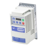
4.5.7.1 Terminal and Protection Status Display
Parameter P530 allows monitoring of the control terminal
points and common drive conditions:
An illuminated LED segment indicates:
• the protective circuit is active (LED 1)
• the Logic Assertion Switch is set to High (+)
• input terminal is asserted (LED 2)
• output terminal is energized (LED 4)
• the Charge Relay is not a terminal, this segment will be
illuminated when the Charge Relay is energized (LED 4).
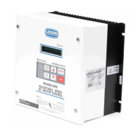
4.5.7.2 Keypad Status Display
Parameter P531 allows monitoring of the keypad pushbuttons:
An illuminated LED segment indicates when the button is
depressed.