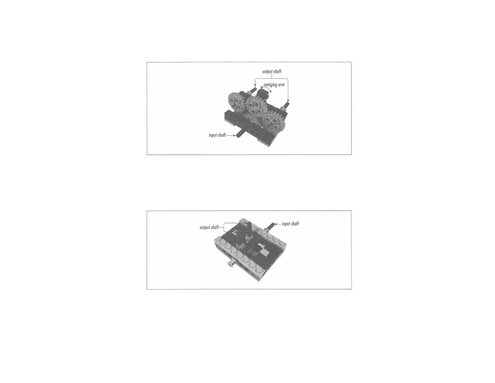
The bottom shaft is the input. A 24t gear mounted on this shaft drives another gear that is mounted on a beam that rotates on the input shaft. Depending on which direction the input shaft turns, the
beam swings to the left or right; the top gear on the beam engages the gear on either the far left or far right. These gears are on the output shafts. You could create variations on this configuration,
using different combinations of gears, but the idea is the same.
This design relies on friction to swing the arm in the right direction. In an ideal, frictionless world, this design would never work.
Page 108
Figure 5-3.
Cutaway view of a swing-arm directional transmission
Worm Gear Design
Minerva's drivetrain is based on a worm gear directional transmission. The basic design of the worm gear directional transmission is quite simple. A cutaway view is shown in Figure 5-4.
Figure 5-4.
Cutaway view of a worm gear directional transmission
The input shaft drives the worm gear, which slides freely along the shaft. In fact, it's easier for the worm gear to slide on its shaft than to turn one of the output shafts. Depending on which way the
input shaft turns, the worm gear slides as far as it can in one direction or the other. When it can't slide any more (because it's hit a beam), the worm gear will turn one of the output shafts.
Minerva actually uses a modified version of this design with four outputs. The worm gear engages two outputs at a time, as shown in Figure 5-5.