44-89a
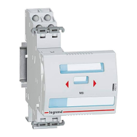
Dimensions of din-rail equipment
B
G
D
45
E
C
A
F
45
E
D
F
B
A B C D E F G
Product
1P 1P+ N 2P 3P 4P
RX
3
MCBs 71.7 17.7 35.4 35.4 53.1 70.8 61 83 44 77.8 88.9
RX
3
RCCBs 71.7 35.6 71.2 61 83 44 77.8 88.9
TX
3
MCBs 71.7 17.7 35.4 35.4 53.1 70.8 61 83 44 77.8 88.9
TX
3
RCCBs 71.7 35.6 71.2 61 83 44 77.8 88.9
Isolating switches DX
3
71.7 17.8
17.8/
35.4
35.6/
53.1
35.6/
70.8
61 83 44 77.8 94.8
Remote trip head isolating
switches DX
3
up to 63A -
1 mod/pole
71.7 35.4 53.1 70.8 61 83 44 77.9 94.8
Remote trip head isolating
switches DX
3
100/125A - 1.5
mod/pole
73 80.1 106.8 61 96 47 79 104.3
DX
3
RCCBs 71.7 35.6 71.2 61 83 44 77.8 94.8
1P DX
3
RCBOs (up to 45A) 68 17.7 60 115 48 74 126.8
1P+N DX
3
RCBOs (up to 40A)
& 4P (up to 32A)
71.7 35.6 71.2 61 83 44 77.8 94.8
2P & 4P DX
3
RCBOs
(40A to 63A)
72 71.2 124.6 61 96 44 78.2 107.8
1P+N DX
3
MCBs 1 mod 71.7 17.8 61 83 44 77.8 94.8
DX
3
MCBs - 1 mod/pole 71.7 17.7 35.4 35.4 53.1 70.8 61 83 44 77.8 94.8
DX
3
MCBs - 1,5 mod/pole 73.1 26.7 53.4 80.1 106.8 61 100 47 79 104.3
DX
3
add-on modules up
to 63A - 1 mod/pole
72 35.6 53.4 53.4 61 96 44 78.2 107.8
DX
3
add-on modules up
to 63A - 1.5 mod/pole
72 35.6 53.4 53.4 61 96 47 78.2 116.7
DX
3
add-on modules 80
to 125A - 1.5 mod/pole
72 71.2 106.8 106.8 61 114 47 78.2 129
DX
3
auxiliaries 71.5 8.8 / 17.7 61 83 44 77.7 84.5
DX
3
remote control 74.3 17.7 / 35.4 61 83 44 80.5 98.8
DX
3
Stop&Go automatic
resetting
74.3 35.4 61 83 44 80.5 113.7
Change-over switches 68 17.7 35.6 60 83 44 74 94
CX
3
latching relays 64 17.8 17.8 35.6 35.6 61 84.5 44 70.2 94.8
CX
3
contactors up to 25A
66.3/
61
17.8 17.8 35.6 35.6 61 84.5 44
72.6/
67.3
94.8
CX
3
contactors 40A & 63A 62 35.6 53.4 53.4 60 83 44 68 94
Auxiliaries for CX
3
contactors
and latching relays
61 9/17.8 61 84.5 44 67 84.5
Push-buttons / control
switches
68 17.7 60 83 44 74 94
Indicators 68 17.7 60 83 44 69 94
Bells and buzzers 60 17.7 60 76 44 66 85
Light sensitive switches
Cat.Nos 0 037 21, 4 126 23 60 35.6 60 85 37.5 66 70
Socket outlets 60 44.5 60 83 44 66 92
Time delay relays 60 17.7 60 83 44 66 94
Remote control dimmers
Cat.No 0 036 58 60 36 60 83 44 66 94
Cat.No 0 036 60 60 72 60 83 44 66 94
Cat.No 0 036 71 60 108 60 83 44 66 94
Description A B C D E F
Programmable
0 037 05 60 17.8 60 83 44 66
time switches
4 127 80/90/94 60 17.8 60 83 44 66
4 127 95, 4 128 12/13 60 53 60 83 44 66
4 126 31/33/41 60 35.6 60 83 44 66
4 126 54/57 60 35.6 60 83 44 66
0 047 70 60 90 60 83 44 66
Transformers and power supplies
0 042 10/30/31 60 72 60 83 44 66
4 130 91 60 35.8 60 83.5 44 66
4 130 92/93/96 60 71.5 60 83.5 44 66
4 130 98 60 89 60 94 44 66
0 047 91/92 60 105 60 95 44 66
4 131 05/06/07/08 60 89 60 95 44 66
0 047 93 60 70 60 95 44 66
Residual current relay
0 260 88 60 35.5 60 89 44 66
 Loading...