2/5
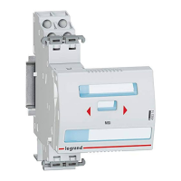
STOP & GO automatic resetting
STOP & GO automatic resettingSTOP & GO automatic resetting
STOP & GO automatic resetting
Cat. N°(s)
Cat. N°(s)Cat. N°(s)
Cat. N°(s)
: 4
: 4: 4
: 4
062 88 / 89
062 88 / 89062 88 / 89
062 88 / 89
4.
4. 4.
4. PREPARATION
PREPARATIONPREPARATION
PREPARATION
-
--
-
CONNECTION
CONNECTIONCONNECTION
CONNECTION
(continued):
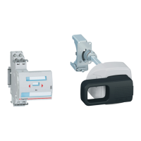
Association:
Association:Association:
Association:
. To be fitted to the left of MCB’s DX
3
3 3
3
≤
10 000A (P+N, 1P, 2P - 1
module per pole wide), RCCB’s DX
3
3 3
3
2P and RCBO’s DX
3
3 3
3
≤
10 000A
(P+N et 2P
≤
63A)
. No tool required. Clipped to the associated device by mean of
plastic clamps.
Wiring diagram:
Wiring diagram:Wiring diagram:
Wiring diagram:
Protection of
Protection of Protection of
Protection of STOP&GO:
STOP&GO:STOP&GO:
STOP&GO:
. It is not necessary to install specific protections upstream of the
Stop & Go because it is self-protected
Connection:
Connection:Connection:
Connection:
. Terminals protected against accidental contact (IP20, wired device).
De
DeDe
Dep
pp
pth
thth
th of terminals
of terminals of terminals
of terminals
:
::
:
. 10 mm.
Connectable section:
Connectable section:Connectable section:
Connectable section:
Copper cables
Without ferrule With ferrule
Rigid cable
1 x 2,5mm²
1 x 2,5mm²1 x 2,5mm²
1 x 2,5mm²
2 x 1,5mm²
2 x 1,5mm²2 x 1,5mm²
2 x 1,5mm²
-
--
-
Flexible cable
1 x 2,5mm²
1 x 2,5mm²1 x 2,5mm²
1 x 2,5mm²
2 x 1,5mm²
2 x 1,5mm²2 x 1,5mm²
2 x 1,5mm²
1 x 2,5mm²
1 x 2,5mm²1 x 2,5mm²
1 x 2,5mm²
2 x 1,5mm²
2 x 1,5mm²2 x 1,5mm²
2 x 1,5mm²
4.
4. 4.
4. PREPARATION
PREPARATIONPREPARATION
PREPARATION
-
--
-
CONNECTION
CONNECTIONCONNECTION
CONNECTION
(continued):
Stripping length recommended:
Stripping length recommended:Stripping length recommended:
Stripping length recommended:
. 7 mm.
Screw head:
Screw head:Screw head:
Screw head:
. Slotted, diameter 3.5 mm.
Recommended tightening torque:
Recommended tightening torque:Recommended tightening torque:
Recommended tightening torque:
. 0.4÷0.5 Nm.
Tools required:
Tools required:Tools required:
Tools required:
. For the terminals: flat screwdriver 3.5 mm.
. For fixing: flat screwdriver 5.5 mm (6 mm maximum).
Lockout:
Lockout:Lockout:
Lockout:
. By the sliding front face.
Sliding front face downward: the associated device goes into OFF
position and manual or automatic closing operations are disabled.
Sliding front face upward: the device is operating.
. Lockout by padlock Φ4mm only when the sliding front face is down.
Then mechanical and electrical controls are not possible.
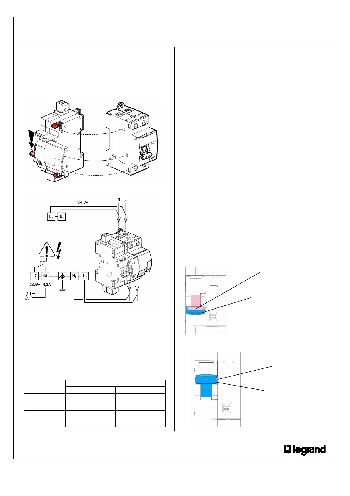
Display of the device status and the status of the contact
Display of the device status and the status of the contactDisplay of the device status and the status of the contact
Display of the device status and the status of the contacts
ss
s of
of of
of
the associated device:
the associated device:the associated device:
the associated device:
. By handle mark:
“O-Off“ white on a green background = device switched-off and
contacts opened.
“I-On” white on a red background = device powered-on and
contacts closed.
Device handle status
Device handle statusDevice handle status
Device handle status:
::
:
. The handle of the Stop & Go automatic resetting module, consists of
two parts:
- an “isolating” handle
- a “power” handle
. Operation sequences:
- Normal operation: both handle upward.
Technical data sheet: F01284EN/00 Updated: - Created: 11/11/2011
 Loading...