3/5
STOP & GO automatic resetting
STOP & GO automatic resettingSTOP & GO automatic resetting
STOP & GO automatic resetting
Cat. N°(s)
Cat. N°(s)Cat. N°(s)
Cat. N°(s)
: 4
: 4: 4
: 4
062 88 / 89
062 88 / 89062 88 / 89
062 88 / 89
4.
4. 4.
4. PREPARATION
PREPARATIONPREPARATION
PREPARATION
-
--
-
CONNECT
CONNECTCONNECT
CONNECTION
IONION
ION
(continued):
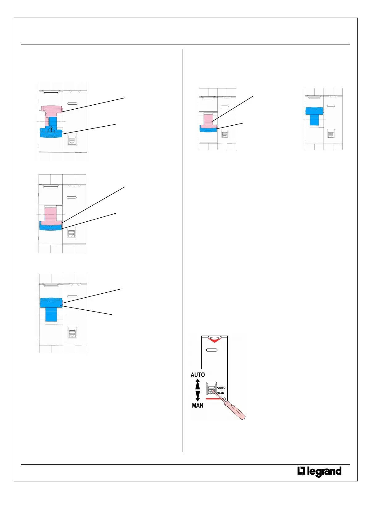
- In case of an unwanted tripping of the associated device and
during the verification of the state of the electric circuit:
The power handle is down.
The isolating handle is up.
- If the Stop & Go detects a permanent fault after a tripping, the
isolating handle goes down
- If the Stop & Go doesn’t detect a permanent fault, it returns to
normal operation (reset of the associated device): both handle
are upward.
WARNING
WARNINGWARNING
WARNING
:
: :
: the stop & go makes only one attempt of resetting.
Time of a re
Time of a reTime of a re
Time of a re-
--
-setting
settingsetting
setting cycle
cycle cycle
cycle:
: :
:
. <
. <. <
. <
2 sec
Tripping
TrippingTripping
Tripping by the test button of the
by the test button of the by the test button of the
by the test button of the associated residual current
associated residual currentassociated residual current
associated residual current
device
devicedevice
device:
::
:
. In auto mode, when tripping the associated device by the test
button, if the test button has been pushed more than 1 second, the
Stop & Go unit will reset the associated device then switch it off
again. It will be necessary to manually reset the Stop & Go.
4.
4. 4.
4. PREPARATION
PREPARATIONPREPARATION
PREPARATION
-
--
-
CONNECTION
CONNECTIONCONNECTION
CONNECTION
(continued):
Resetting by the Stop & Go handle
Resetting by the Stop & Go handleResetting by the Stop & Go handle
Resetting by the Stop & Go handle:
::
:
. When the permanent fault has disappeared, the resetting of the Stop
& Go and of the associated device is carried out by the Stop & Go
handle (isolating and power handles together)
Selector AUTO / MAN:
Selector AUTO / MAN:Selector AUTO / MAN:
Selector AUTO / MAN:
. The selector enables and disables the automatic remote control.
. Positions:
- AUTO: possibility to automatically or manually control tripping and
re-setting.
- MAN: manual control only by the handle of the Stop & Go (isolating
and power handles together)
. Signalling by LED:
- Green fixed: associated device “power on” and “Stop & Go” in AUTO
mode.
- Green flashing: “Stop & Go” in MAN mode.
Signalling:
Signalling:Signalling:
Signalling:
. Signalling by LED:
- Green fixed: associated device “power on” and “Stop & Go” in AUTO
mode. Automatic resetting activated (and self-test activated for cat. n°
4 062 89).
- Green flashing: “Stop & Go” in MAN mode.
- Red flashing: waiting for reset.
- Red fixed: the device has tripped on fault (overload, short-circuit,
residual current fault) or by control auxiliary.
- Sliding front face downward: LED switched-off.
- Yellow fixed (cat. n° 4 062 89 only): self-test function has detected a
malfunction of the associated differential device.
Self
SelfSelf
Self-
--
-test programming
test programmingtest programming
test programming (
( (
(cat. n°
cat. n°cat. n°
cat. n° 4
4 4
4
062 89):
062 89):062 89):
062 89):
. After having connected cat. N° 4 068 89 to
230 V ~ network, put the handle on ON
position, switch the selector from “AUTO”
position to “MAN” position then again to
“AUTO” position.
. The first automatic test of the residual
current detection is carried out
instantaneously. The next test will be
carried out 56 days and 8 hours after the
first test and this test will be shift during the
night. Then the next test will occur every 56
days (8 weeks).
Technical data sheet: F01284EN/00 Updated: - Created: 11/11/2011
 Loading...