5/5
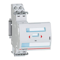
STOP & GO automatic
STOP & GO automatic STOP & GO automatic
STOP & GO automatic resetting
resettingresetting
resetting
Cat. N°(s)
Cat. N°(s)Cat. N°(s)
Cat. N°(s)
: 4
: 4: 4
: 4
062 88 / 89
062 88 / 89062 88 / 89
062 88 / 89
5. GENERAL CHARACTERISTICS
5. GENERAL CHARACTERISTICS 5. GENERAL CHARACTERISTICS
5. GENERAL CHARACTERISTICS
(continued)
Resistance to sinusoidal vibrations:
Resistance to sinusoidal vibrations:Resistance to sinusoidal vibrations:
Resistance to sinusoidal vibrations:
. According to IEC 60068-2-6.
. Axis : x, y, z.
. Frequency range: 5÷100 Hz ; duration 90 min.
. Displacement (5÷13.2 Hz) : 1mm
. Acceleration (13.2÷100 Hz) : 0.7g (g=9.81 m/s
2
).
Maximum power consumption:
Maximum power consumption:Maximum power consumption:
Maximum power consumption:
. <20VA rms (<80VA peak) during resetting
Standby power consumption:
Standby power consumption:Standby power consumption:
Standby power consumption:
. <1,5VA
Recognition:
Recognition:Recognition:
Recognition:
. Labelling of the circuits by label in the "label holder" on the front-side of the device.
6. CO
6. CO6. CO
6. CON
NN
NFORMITIES AND APPROVALS
FORMITIES AND APPROVALSFORMITIES AND APPROVALS
FORMITIES AND APPROVALS
Compliance with
Compliance withCompliance with
Compliance with standard
standard standard
standards
ss
s:
::
:
. CEE guidelines : 73/23/CEE + 93/68/CEE
. IEC / EN 50557: device for automatic reset of MCB’s, RCBO’s, RCCB’s for household and similar purposes.
. Electromagnetic compatibility: EN 61543
. Legrand devices can be used under the conditions of use as defined by IEC / EN 60947.
7.
7. 7.
7. AUXILIARIES
AUXILIARIESAUXILIARIES
AUXILIARIES AND ACCESSORIES
AND ACCESSORIES AND ACCESSORIES
AND ACCESSORIES
Signal
SignalSignal
Signalling
lingling
ling auxiliaries:
auxiliaries: auxiliaries:
auxiliaries:
. Auxiliary contact (½ module – cat n° 4 062 58).
. Fault signalling changeover switch (½ module – cat n° 4 062 60).
. Auxiliary contact modifiable in default signal (½ module – cat n° 4 062 62).
. Auxiliary contact + fault signalling switch - can be modified to 2 auxiliary contacts (1 module - cat n° 4 062 66).
Control auxiliaries:
Control auxiliaries:Control auxiliaries:
Control auxiliaries:
. It is forbidden to associate control auxiliaries (cat. n° 4 062 7x / 8x) to motor driven control module with integrated automatic resetting.
Possible combinations with
Possible combinations withPossible combinations with
Possible combinations with signal
signal signal
signalling
lingling
ling auxiliaries:
auxiliaries: auxiliaries:
auxiliaries:
. Auxiliaries are clipped on the left side of the Stop & Go unit
. Two signalling auxiliaries max. (cat. n° 4 062 58 / 60 / 62 / 66).
. If two signalling auxiliaries are associated to a same motor driven control unit, the 1 module wide control auxiliary (cat n° 4 062 66 / 78 / 82 / 84)
must be located to the left of the ½ module wide auxiliary (cat. n° 4 062 58 / 60 / 62).
Technical data sheet: F01284EN/00 Updated: - Created: 11/11/2011
 Loading...