2
PLACEMENT GUIDELINES
Depending upon obstacles such as furniture or partitions, the area of coverage may be less
or more than the sensing distances shown in the coverage pattern. This must be considered
when planning the number of sensors and their placement. It is also recommended to place
the sensor 4 to 6 feet away from air supply ducts.
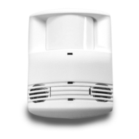
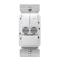
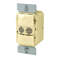
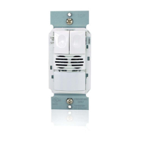
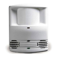
The DT-205 is designed for a ceiling height of about 8-10 feet. Mounting above or below this
range will significantly affect the coverage patterns. As a general rule, each occupant should
be able to clearly view the sensor.
Masking the PIR Lens: Opaque adhesive tape is supplied so that sections of the PIR lens
can be masked. This restricts the sensor’s view and allows you to eliminate PIR coverage
in unwanted areas such as hallways outside of the desired coverage area. Since masking
removes bands of coverage, remember to take this into account when troubleshooting
coverage problems. The Ultrasonic coverage cannot be masked, but you can adjust its
sensitivity to reduce the coverage area.
WIRING DIRECTIONS
Each Wattstopper B347-D power pack can supply power for up to 2 DT-205 sensors. Each Wattstopper BZ series power pack can
supply power for 3 DT-205 sensors. When using more sensors than this, multiple power packs are required.
Refer to the wiring diagram on the next page for the following procedures:
Connect the LOW VOLTAGE:
• RED wire (+24VDC) from power pack to the red wire on the sensor.
• BLACK wire (Return) from power pack to the black wire on the sensor.
Wiring a single lighting load controlled by occupancy–connect:
• BLUE wire from power pack to the blue wire on the sensor.
To add a MOMENTARY MANUAL SWITCH such as the LVS-1 Momentary Toggle Switch, to the above applications–connect:
• Wire from one side of switch to the gray wire on sensor.
• Wire from other side of switch to the red wire on sensor.
WARNING: TURN THE POWER OFF AT THE
CIRCUIT BREAKER BEFORE WIRING.
Low Voltage Wires
Control Output (Blue)
Common (Black)
+24VDC (Red)
Neutral
Hot
White
Black
Red
Black
Power Pack
Blue
Red
Red
Fixture
BZ-200
**Ground
*To
Additional
Sensor(s)
** BZ-200 Power Pack
must be grounded to
ensure signal integrity,
not for safety ground.
Optional
Local Off
Switch
Fixture
Optional
Local Off
Switch
DT-205
Low Voltage
Occupancy
Sensor
Gray
Red
Red
Hot
Neutral
Black
White
Power Pack
BZ-250
Brown
Black
Grey
Orange
Red
Blue
Cap
Cap
COM
SW1
LVSW-101
Low Voltage
Switch Input
** BZ-250 Power Pack
must be grounded to
ensure signal integrity,
not for safety ground.
**Ground
Fixture A
(A)
Auto
ON
Man
ON
Low Voltage
Wires
Control Output (Blue)
Common (Black)
+24VDC (Red)
*To
Additional
Sensor(s)
Gray
DT-205
Low Voltage
Occupancy
Sensor
Manual-On wiring with low voltage momentary switch
One sensor, conference room
 Loading...