3
Using a 4-Inch Square Junction Box
1. Pull the line voltage wires into the J-Box through the conduit
knockout.
2. Run the wires through the CA-1 adapter then connect the
line voltage wires to the appropriate terminals on the sensor.
3. Align the CA-1 and the sensor with the J-Box so that the
mounting screw tabs on the box match the mounting holes
on the sensor’s rear housing and the CA-1.
4. Use two machine screws (included with the sensor) to attach
the sensor to the mounting tabs on the J-Box.
5. Snap the front cover onto the sensor.
Using an Octagonal J-Box
1. Pull the line voltage wires into the J-Box through the conduit
knockout.
2. Connect the line voltage wires to the appropriate terminals
on the sensor.
3. Loosen the appliance mounting screws attached to the J-Box
4. Align the sensor in the J-Box so that the mounting screws on
the box match the key holes on the sensor’s rear housing.
5. Push the sensor up into the J -Box and twist it so that the
mounting screws are seated in the keyhole slots.
6. Tighten the two screws to secure the sensor to the J-Box.
7. Snap the front cover onto the sensor.
* The
Junction
Box must
be at least
2.25” deep.
If it is not,
an extension
ring is
required.
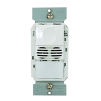
2.25" Deep
*
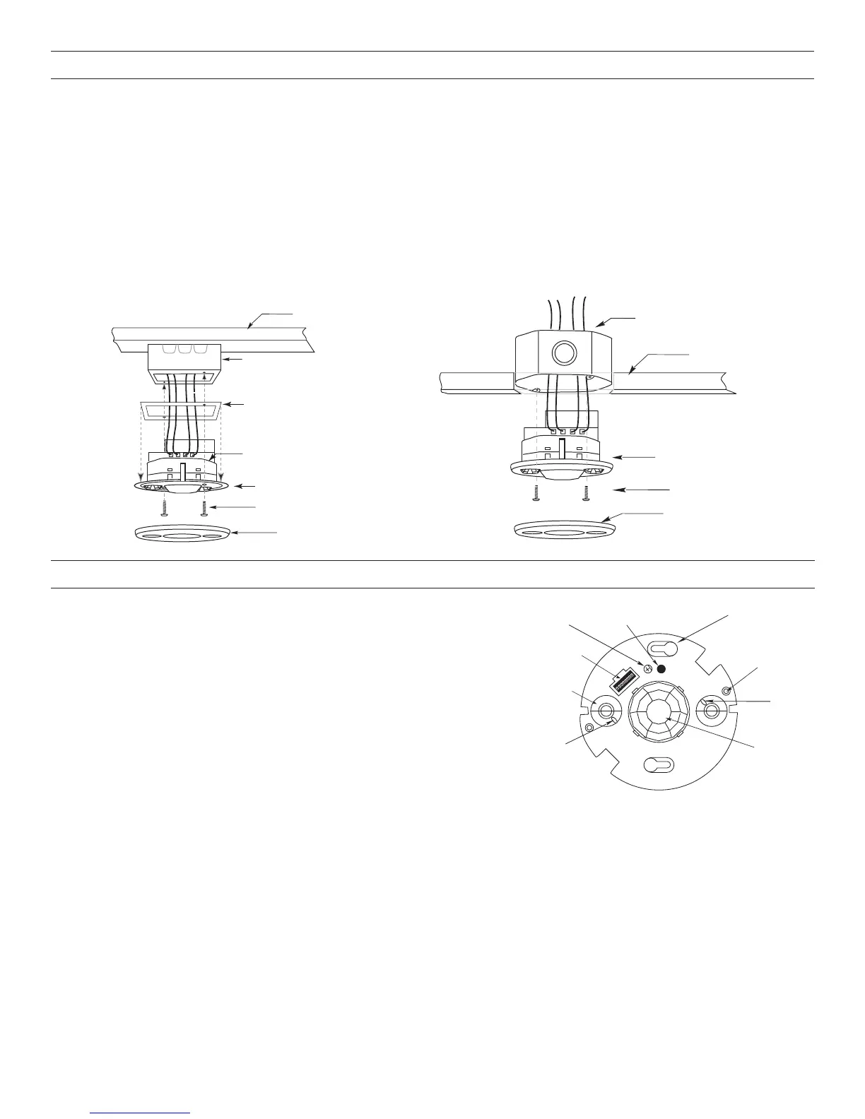
Junction Box
Ceiling
Sensor
Screws
Front
Cover
Mounting to an Octagonal Junction Box
Rear Housing
4" Square
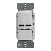
Wiremold #V5752 bo
Front Cover
Screws
CA-1 Adapter
Sensor Flange
Mounting to a 4” Square Wiremold V5752 box or 4”
Square Junction Box with Double-Gang Mudring
MOUNTING THE SENSOR
SENSOR ADJUSTMENT
NOTE: This unit is pre-set for basic operation as described in this guide.
Adjustment is optional.
The sensors are factory preset to allow for quick installation in most
applications. Verification of proper wiring or coverage, or customizing the
sensor’s settings can be done using the following procedures. To make
adjustments, open the Front Cover with a small screwdriver.
There is a 30 second warm-up period when power is first applied.
Before making adjustments, make sure the office furniture is installed,
lighting circuits are turned on, and the HVAC systems are in the overridden/
on position. VAV systems should be set to their highest airflow. Set the Logic
Configuration and Time Delay to the desired settings. See the DIP switch
Configuration Chart.
To Test Occupancy Sensors
1. Ensure the Time Delay is set for Test Mode* using the “Test Mode/20 minutes” setting. (DIP switches 1, 2, & 3 are OFF).
2. Ensure that the Light Level is at default (maximum). Press and hold the pushbutton for 5 seconds or until the Green LED flashes
rapidly. Wait 10 seconds for the flashing to stop.
3. Ensure that the Ultrasonic Sensitivity trimpot is set to about 70%, clockwise.
4. Remain still. The red and green LEDs should not flash. The lights should turn off after 5 seconds. (If not, see “Troubleshooting”).
5. Move around within the coverage area. The lights should come on. Adjust the Ultrasonic Sensitivity as necessary to provide the
desired coverage (Green LED indicates activation from the ultrasonic sensor).
When testing and adjustment is complete, reset DIP Switches and Light Level to the desired settings, and replace the cover on the
sensor.
• Test Mode is a temporary state that starts when you first set the sensor’s DIP switches for the “Test Mode/20 minutes” (switches 1,
2, 3 OFF). If you need to invoke the Test Mode and the DIP switches are already set for Test Mode/20 minutes, toggle DIP switch 1
ON then back to the OFF position. This provides a 10 minute test period. During the test period, the Time Delay is only 5 seconds.
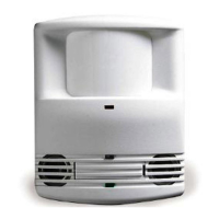
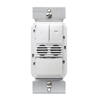
Keyhole slots
(for mounting to
4" octagonal box)
Double gang
mudring
mounting holes
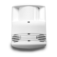
Light level pushbutton
DIP switches
PIR lens
Ultrasonic
sensitivity
trimpot
ON
1
2
3
4
5
6
7
8
ECE
Ultrasonic
transducer
cones
Ultrasonic
activity
LED (Green)
PIR Activity
LED (Red)
 Loading...