3
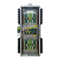
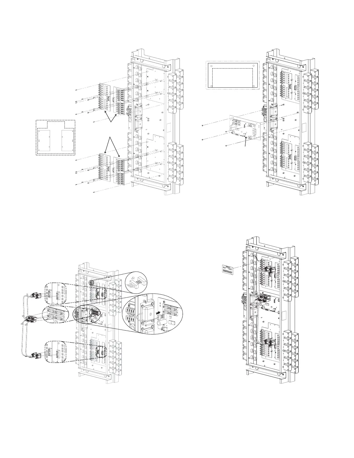
Step 5:
• Connect LMRD to LMPI.
• Connect relays to LMRD card.
• Connect power to LMPI.
(See Relay Connection Details for DIP Switch settings.)
Step 6: Apply upgrade label.
Fig. 13: Connection details Fig. 14: Label location suggestion
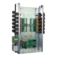
Step 4: Install LMRD and LMPI cards.
CAUTION: Do not overtighten screws
Fig. 12: Mounting detail
Mounting plate screw locations
(Total 4 #6-32 screws for
mounting plate)
LMPI-ASSY
(P/N #770431)
Mounting plate screw
locations (Total 24 X
# 4-40 screw fo
r
LMRD-12
(P/N #16694)
Power supply connection detail
 Loading...