2
PIR
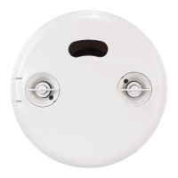
32 ft
Ultrasonic
25 ft x 25 ft
COVERAGE PATTERN
The LMDC-100 provides a 360° coverage pattern. The coverage shown represents maximum coverage for walking motion at a
mounting height of 10 feet.
PIR Coverage
Ultrasonic
Coverage
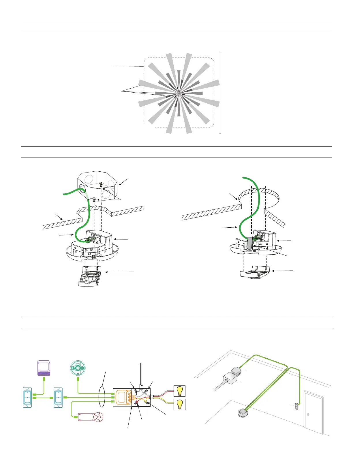
Rear
housing
4" Octagonal J-Box
(at least 1.5" deep)
Front cover
Ceiling
Ceiling hole
LMRJ cable
Spring clips (2)
Screws
For applications requiring plenum rating No box required in non-plenum rated applications
Rear
housing
MOUNTING
To octagon box: Through ceiling tile:
WARNING: A junction box used for sensor installation must not contain any Class 1, Class 3, or other power or lighting line voltage
circuits.
CONNECTIVITY
The illustrations below show examples of free-topology wiring. The LMDC-100 communicates to all other Digital Lighting Management
devices connected to the low voltage DLM Local Network, regardless of their position on the DLM Local Network.
Line
Voltage
Room
Controller
Daylight Sensor
Switch
Sensor
Sensor
DLM Local Network
Low Voltage
LMRJ Cables
Loads
2
1
Line/Hot
Black wire
Neutral
White wire
Red wire
to Load A (1)
Yellow wire
LMRC
102
Room
Controller
J Box
Ceiling Mount
Occupancy
Sensor
Switch
To
Load
 Loading...